
User's Manual


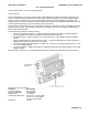


Table Of Contents

APPLICANT: MOTOROLA EQUIPMENT TYPE: ABZ89FC3793
User / Operational Manual
Functional Description / Operation of Modules (Draft)
EXHIBIT D1-6
Power Amplifier Module Overview
The Power Amplifier (PA) is a forced convection-cooled RF power amplifier. It accepts a low-level modulated RF
signal from the Exciter Module, and amplifies it for transmission via the site transmit antenna port. The PA is non-
linear, and is therefore used for continuous wave (CW) applications only. The output power is continually
monitored and regulated by a feedback and control loop, with a power output control voltage being generated by
the transmitter control circuitry located on the PA Input/Output boards.
Overview of Circuitry
The Power Amplifier contains the following sub-circuits:
• DC Distribution Board – main interface for the PA to the Station Control Module (SCM) and Power Supply
(PS). This board contains PA SPI circuits including Analog to Digital Converter (ADC), Digital to Analog
Converter (DAC), and Non-Volatile Memory (NVM) devices, and hardware (HW) metering circuitry
• RF Board – provides RF signal amplification from the Exciter Module low-level signal to the BR output
power level
• Isolator – protects the PA from damage when poor RF load conditions exist. Also assists with
intermodulation attenuation performance
• Output Board – performs harmonic filtering and RF power detection functions, and routes the RF signal to
the antenna port
Input and Output Connections
The following shows the PA input and output external connections.