WIN\MMIMAN1.
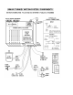
INTRODUCTION MMI Multi-Axes Motion Controllers provide control of up to eight step motors. Each motor controller is independent. Each supports a home sensor, limit safety loop, and six bits of general purpose I/O (input/output). In addition, up to eight MMI motion controllers can be "daisychained" together with simple pin-to-pin DB9 serial cables for a total of 64 motors per serial port.
DANGER SUDDEN AND UNEXPECTED MOTION CAN OCCUR DUE TO PROGRAMMING ERRORS. STAY CLEAR OF THE MOTORS. WARNING It is the user's responsibility to insure that commands are not sent to busy systems. The motion systems can indicate they are busy but have no way to block incoming commmunications which will either be lost or jam (lock-up) the system. In some cases, the system may begin uncontrolled motion. ATTENTION CONTRARY TO POPULAR PRACTICE, IT IS BEST TO READ THIS MANUAL BEFORE ATTEMPTING TO OPERATE SYSTEM.
SECTION 2: SR4 - Serial Repeater 4/channel Assembly CONTENTS Introduction Hardware Configuration Service Access Table of ID and Status Codes Displays & Controls Mechanical Assembly PAGE 7 8 8 11 12 14 SR4 (CY 233) COMMAND SET SUMMARY WRITE READ ECHO ENTER W R J < Send commands to the motion system. Read status (busy) of the motion systems. Used to set SR-4s into pass-through mode. Carriage Return terminates commands.
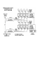
INTRODUCTION In the MMI system, two SR4 controllers are used. Each can control up to four SMC systems. During operation, a three byte net command (address), consisting of three bytes, is prefixed to a motion control command string. When the selected SR4 detects its address, a serial path is connected to the addressed SMC by a 1 to 4 serial data multiplexer. The motion command is then passed to the SMC. The command terminator character (carriage return) resets the multiplexer.
HARDWARE DESCRIPTION The MMI network control contains two CY233 SR4 cards, generally refered to as #0 and #1 which is their binary address. Each card controls four SMC motor systems and includes status LEDs and jumber posts (dip-clips) for setting its ID number. The cards are mounted to a single rail and can be removed as a single unit as required during service.
WRITE MODE In general, SR4 mode commands are prefixed to SMC motion commands which are then "passed through" to the motion systems. Only two mode commands are used in this system, the write (W) and the read (R). A write command consists of a mode character (W), an ID number (two hex characters), a command string (motion system data string), and a terminator (carriage return). The ID number consists of two characters; the first or high byte is the system ID. This identifies an MMI net controller card.
ECHO MODE In the MMI network system, with two network cards, it is necessary to engage the CY233 passthrough (echo-all) mode. This allows commands originating in a motion channel (SMC) to be passed through successive SR4 cards down-stream in the network loop. A typical example is the SMC system query commands. The J command format consists of a mode character (J), the ID number (two hex characters; the second is always F), and the terminator (carriage return).
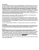
TABLE OF ID AND STATUS CODES
LED DISPLAYS The displays are used with the test software program to verify and demonstrate correct operation of the MMI. They are located on each SR4 card; inside the MMI.
SECTION 3: SMC - STEP MOTION CONTROLLER ASSEMBLY ALSO REFER TO: Cybernetic Micro Systems - CY 545 Step Motor Controller Manual MMIDEMO program - Software Listings & Comments CONTENTS Introduction Hardware Configuration Displays & Controls Installation & Test Programming & Listings Serial Cable Diagrams PAGE 17 19 20 21 25 26 CY 545 COMMAND SET SUMMARY (In the MMI network system, all letter commands must be in lower case) Command Function Note A val 24 B bit # C D val 16 E F val G H bit # I J add L cnt
!!!! ATTENTION !!!! Mis-wiring of motor or power supplies WILL damage motor drivers IMMEDIATELY. Motor coils A or B can be reversed; motor will run in the opposite direction. Pairs can be reversed; pair A in coil B for example. CROSS-WIRING, an A and B wire crossed, WILL damage driver. Allowing exposed motor leads to touch each other, ground, or power MAY damage driver. Refer to Appendix D in the MS driver section for wiring schemes. SMOKE, POPPING, ELECTRONIC ODOR, OR FUSE FAILURE INDICATES DRIVER FAILURE.
Introduction The SMC motion control system consists of two basic elements; the controller card and the MS driver card. The controller card (CY5.4) contains the Cybernetic CY 545 or CY 550 Step Motor Controller and a 2K character EEPROM (non-volatile) for storing application routines. Refer to the Cybernetics 545 manual for a description of the 545 microprocessor and its "High-Level" command set (26 characters and symbols). All actions of this system are controlled by these commands.
Hardware Configuration The SMC controller card contains the CY 545 motion controller, EEprom memory, memory latches (2 each), RS-232 receiver / driver, LED status lites and standard crystal (11 MHZ). Refer to the Rate Table in the CY545 manual. Serial Format The SMC is connected as a RS-232 serial device and communicates with the host computer through the SR4 network. The serial format is configured in the following manner: ASCII characters, 1200 Baud, 8 data bits, no parity, and one stop bit.
I/O Function. The Cybernetic User Bits are available at the CI cable connectors and can be used as either inputs or outputs dependent on the command. Note that an output can only drive LEDs such as those in Solid-State relays or optical isolation. An input can only be a passive switch or isolated relay contact across the User Bit and User ground. Connecting any device, at a different potential, to this system through the User Bits, WILL damage the User port; opto-isolation is required.
Reserved and Special Software Commands. CLEAR Writes 0's and CR's to memory. LOAD [F6] Loads memory. Not same function as Basic F3 key. EXIT [F5] Required to close comm port, close file, and clear error traps. comma [,] Do not use comma to separate elements of 545 commands (T,L, and ? M xx). Comma is a Basic symbol; use space instead. [a,b,c] HP-LED command string is not used. C Continuous Step Mode is normally not used with the CY545 unless motion can be terminated with an external Abort signal.
Refer to lines 500-1000 of the listings in this manual. These tests prove that the MMI system is operating correctly. Typically, a motor will run back and forth several times. Observe the LED indicator lites while the tests are running and note that each action of the system can be monitored and that this self-test is the series of commands listed between the quotes in lines 500-1000.
4. Memory Commands. F7 ? y where is memory byte pointer; y=00000 after reset. y 0< sets pointer to byte location 0; if required. ? m 21< displays 21 "command lines" of memory (F8 and type 21<). CLEAR< fill the memory with 0's and carriage returns; STOP commands. YES< yes; wait till 0 0 0 0....DONE. F7 y=0000. F8 21< memory is cleared; all zeros and carriage returns; 42 bytes. F6 load memory; host goes to line 1000; returns ? p when done. F7 y=xxxx; last byte of program.
Programming The software program used with the MMI/SR4/SMC system is only a "Serial Driver" routine. The main purpose of the program is to send and receive commands between the host and the MMI microprocessors. The motion control software (firmware command set) is contained only in the CY545.
Line 2000-2510 assemblies keyboard entries and sends them to the MMI at the Enter key ( CR = carriage return or enter key). Note the special commands at line 2210-2270 which are created commands not part of the MMI command set. Line 2600-2750 reads any incoming characters from the MMI and prints to the host display screen. Line 2910-3000 closes the comm ports on Exit (F5) or a computer error code other than ERROR = 24 (comm port is busy).
Program Listings See MMIDEMO program
Serial Cables XT TYPE. PIN 1 PIN 2 PIN 3 PIN 5 PIN 7 CPU DB-25 (IBM STYLE) CONTROLLER DB-9S (AT) Frame Ground <------------------------> Shell TX Transmit --------------------------> PIN 3 RX Receive <-------------- ---------- PIN 2 CTS Clear <------------------------- PIN 8 Signal Ground <------------------------> PIN 5 DB-25 to DB-9 Adaptor (solder) RX Receive TX Transmit DSR Ready Signal & Frame AT TYPE.
SECTION 4: MMI Mechanical Assembly The MMI assembly consists of the SR4 network controllers, the SMC (CY 5.4 controller & MS 2.0) motor drivers, all DC power supplies, and an AC power entry. The DC power supplies provide +5 vdc TTL computer (VCC) and +40 vdc motor (VMM). The VCC supply is over-current protected. In addition, A 1 amp AC fuse protects the entire assembly. NOTE: NEVER REPLACE THE FUSE. FUSE FAILURE INDICATES DRIVER FAILURE. The green chassis lamp indicates VMM (motor) power on.
msman.
PRODUCT DESCRIPTION. The MM & MS, Series 1 & 2, stepper motor driver, is a switching type, constant- current regulator which drives current pulses through the windings of a stepper motor. All stepper motors are stepped or rotated by changing the direction of the current flow through the windings in a unique sequence. Each change of current direction results in a step. The driver contains two sections: (1) the step generator; and the (2) power drivers.
The digital phase-input (F) level (HI or LO) selects which pair turns on and corresponds to the direction of current flow through the winding. The current controls, (I0 and I1) select one of four comparators; zero, low, medium, or full. The output is therefore a series of current pulses equal in amplitude and separated by the period of fixed time off. The value of the current sense resistor is pre-selected to produce a current amplitude equal to that of the current rating of the motor winding.
GND TS1-4 & 5 P1-19, 3, 5 In all cases, ground is COMMON to all grounds; digital VCC, analog VMM, chassis ground and green wire ground (AC power ground). If a dual (VMM & VCC) supply is used, then an identical and equal ground lead is connected; 2 each wires to TS1-4 and 5. Always bridge the supply returns and connect to chassis. If separate supplies are used, connect the VMM supply and ground to the TS1 connector. Connect the driver VCC (P1-13&14) and ground (P1-19) from the driver to the controller bus.
Spare Inputs P1- 18, 8 & P1- 20, 7 Pins 18 and 20 can be used for other signals to/from the card. See Chassis Signals connector. Pin 20 is normally keyed on free standing cards. (3) Chassis Signals P1- 1 to 9 & P1- 2 to 10 These signals are normally used to provide for a convenient method of cabling the driver between the controller and the motor, power supply, chassis assemblies. Home Sensor Pins P1- 1, 2, 3, 4 These pins power the optical home sensor circuit. SEE APPENDIX A & F.
APPENDIX SECTION
APPENDIX B: DESCRIPTION OF HOMING AND ABORT LOOP PAGE 1/2 HOMING. A major advantage of a digital Open-Loop step system is the ability to operate plus or minus zero steps (no error). Two conditions are required. One is that the motor is sufficient for the load in normal operation and second, that a reference position, commonly called the "home position", be consistently established during initialization of the system.
APPENDIX B: DESCRIPTION OF HOMING AND ABORT LOOP PAGE 2/2 SUPER HOMING. In high resolution systems, two sensors are used. The first sensor, the home sensor, is mounted to the motion platform in the typical configuration. The second sensor, the index sensor, is located as an index detector on the motor shaft. The index can be either a disk with a tab or a long pin. During the homing operation, the motor is stepped backwards until the first sensor is blocked.
APPENDIX C MOTOR CURRENT ADJUST PAGE 1/2
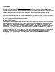
APPENDIX D MOTOR WIRING SCHEMES PAGE 1/2 Performance of a stepper motor based system depends more on the electronic drivers used than it does on the motor itself. A step motor (both PM and Hybrid type) is made to step by sequencing the orientations of the magnetic fields in two coils. The UNIPOLAR drive method of is illustrated, in the figure, using just ONE coil of the motor. Note that the center tap of the coil is connected to the positive motor supply voltage.
APPENDIX E PAGE 1/2
APPENDIX F PAGE 1/2
APPENDIX F PAGE 2/2
APPENDIX I PAGE 1/1 MOLEX - WALDOM NYLON CONNECTOR SYSTEM USED BY THE MOTION GROUP The connectors used on Motion Group equipment are nylon connectors are manufactured by Molex and are refered to as .062 style (pin diameter) or .093 (large driver motors only). They are available from Newark, Allied, and Digi-Key and come in 1 to 36 positions with locking and mounting tabs which snap-in to punched holes on brackets or enclosures. TYPICAL $ POLES TYPE 5.84/10 4 (.062) MALE HOOD 5.95/10 4 (.
SPECIFICATIONS - MMI PARAMETER MIN MAX UNIT Power Motor supply voltage 12 40 VDC Current (no motor) 150 160 ma PWM frequency MD10A 18 24 Khz Motor current MS2.0 0.05 2.0 Amp Step pulse input Voltage 0 +5.0 VDC Sink surrent 12 20 ma Pulse high 1 uSec Pulse low 1 uSec Rise time 0.5 uSec Fall time 0.5 uSec Frequency 500 KHz Logic ' 1' volts +1.8 +2.0 VDC Direction input Voltage 0 +5.0 VDC Sink current 12 20 ma Logic ' 1' volts +1.8 +2.