
User Manual
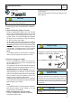
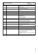
Z2 Thermal-magnetic circuit breaker General switch for the gen-set.
It protects both gen-set and related electrical circuit from over
current /short circuit.
D Ground fault interrupter (30 mA) Device for protection against not-direct contacts for TN and TT
systems (neutral grounded to frame)
N2 G.F.I. and circuit breaker General switch for the gen-set. Works as both circuit breaker
and G.F.I.
V5 (SR) Oil pressure indicator Indicates engine oil pressure (bar).
Z5 (SR) Water temperature indicator Indicates cooling liquid temperature (C).
C2 Fuel level gauge Indicates fuel in the reservoir (%).
H2 Voltage commutator Selection of visualized line voltage.
U7 Engine control unit EP6 Engine control unit.
Genset stop/ start.
Handling of generator alarms.
display of alarms, Voltage, Hz, hour counter, Amps, battery vol-
tage, operation messages.
15 A.C. socket AUX sockets for load connection.
I6 Start Local/Remote selector Selection of engine control in use.
Local start: control on board, EP6 operated.
Remote start: external control, EAS operated.
12 Earth terminal Ground connection point for gen-set.
X1 Remote control socket Connection for TCM35 remote control or for a NO clean contact,
both operating only if EP6 is set to AUTO.
B3 E.A.S. connector Connection for automatic intervention unit (AMF + ATS).
10 pin connector.
L5 Emergency button To be pushed in case of danger. Immediate stop of the gen-set.
R3 Siren Gen-set acoustic alarm.
S7 (SR) Plug 230V single-phase External supply for engine heater (mains).
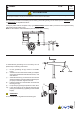
T5 (SR) Earth leakage relay Ground fault interrupt (GFI) relay - Protection device against in-
direct contact for TN systems (GE neutral to ground).
It opens the general circuit breaker, thereby interrupting the po-
wer supply to the electrical system.
The generator does not stop.
The regulations on the GFI must be performed by qualied per-
sonnel.
Q3 Output power terminals Terminal output for load connection.
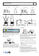
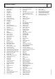
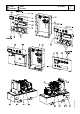
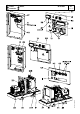
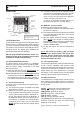
Components of frontal panel GE 35 YSX
GE 35 - 50 PSSX
M
32
REV.1-03/13
23/11/12 84930-GB