language USE AND MAINTENANCE MANUAL TRANSLATION OF THE ORIGINAL INSTRUCTIONS – ENGLISH GE 35 PS SX GE 50 PS SX • • • • Gruppo Elettrogeno Generating Set Groupe Electrogene Grupos Electrógenos M A D E • • • • Stromerzeuger Grupo Gerador Генераторная Установка Stroomaggregaten I N I T A L Y Codice Code Code Codigo Kodezahl Código Код Code 848319003 Edizione Edition Édition Edición Ausgabe Edição Издание Editie 02.
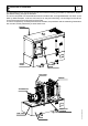
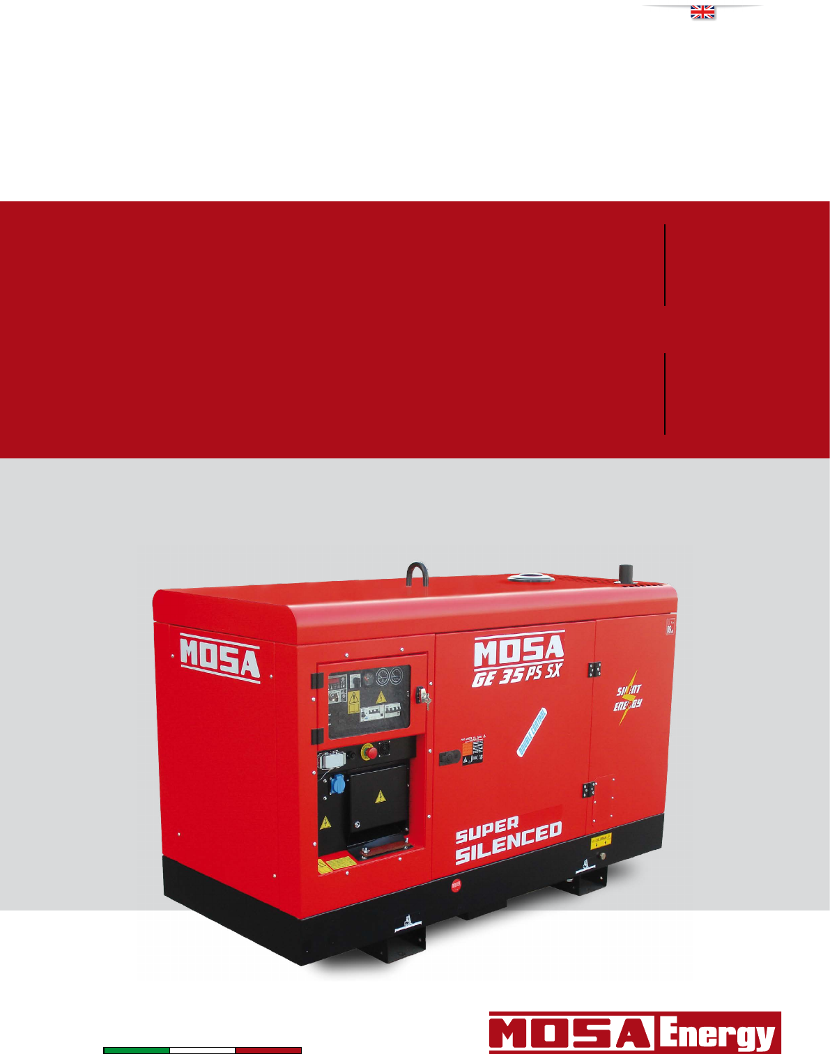
M 0 DESCRIPTION OF THE MACHINE REV.0-10/14 The generating set is a unit which transforms the mechanical energy, generated by endothermic engine, into electric energy, through an alternator. The unit is composed of a structured base which includes a tank, an engine/alternator unit fixed on the base by elastic dampers, a roll-bar, with hook for an easy and sure lifting, a chest hinged to the roll-bar for a quick access to the engine and to the air filter.
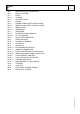
M 1 INDEX REV.
M 1.01 Copyright REV.0-10/02 ! ATTENTION This use and maintenance manual is an important part of the machines in question. The assistance and maintenance personel must keep said manual at disposal, as well as that for the engine and alternator (if the machine is synchronous) and all other documentation about the machine. We advise you to pay attention to the pages concerning the security (see page M1.1). All rights are reserved to said Company. It is a property logo of MOSA division of B.C.S. S.p.
Notes M 1-1 REV.1-03/14 INFORMATION Dear Customer, We wish to thank you for having bought a high quality set. Our sections for Technical Service and Spare Parts will work at best to help you if it were necessary. To this purpose we advise you, for all control and overhaul operations, to turn to the nearest authorized Service Centre, where you will obtain a prompt and specialized intervention.
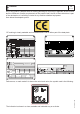
M 1.4 CE MARKING REV.7-02/14 Any of our product is labelled with CE marking attesting its conformity to appliable directives and also the fulfillment of safety requirements of the product itself; the list of these directives is part of the declaration of conformity included in any machine standard equipment. Here below the adopted symbol: CE marking is clearly readable and unerasable and it can be either part of the data-plate. TYPE SERIAL N° Made in UE-ITALY TYPE/N° VOLTAGE(V) POWER(W) Hz G P.F.
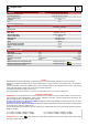
M 1.5 TECHNICAL DATA REV.0-10/14 GENERATOR *Stand-by three-phase power *PRP three-phase power *PRP single-phase power Frequency Cos ϕ GE 35 PSSX 33 kVA (26.4 kW) / 400 V / 47.6 A 30 kVA (24 kW) / 400 V / 43.3 A 11 kVA / 230 V / 47.6 A 50 Hz 0.8 GE 35 PSSX (vers.
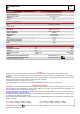
M 1.5 TECHNICAL DATA REV.0-02/16 GENERATOR *Stand-by three-phase power *PRP three-phase power *PRP single-phase power Frequency Cos ϕ GE 50 PSSX 51 kVA (40.8 kW) / 400 V / 73.6 A 46 kVA (36.8 kW) / 400 V / 66.4 A 17 kVA / 230 V / 73.9 A 50 Hz 0.8 GE 50 PSSX (vers.
M 2 WARNINGS REV.1-02/14 The installation and general warnings regarding operations are aimed achieving correct use of the machine and/or apparatus in the place where it is used as a genset and/or motor welder. - Advice to the User about the safety: + NB: The information contained in the manual can be changed without notice. Any damage caused in connection with the use of these instructions shall not be considered as they are only indicative.
M 2-1 SYMBOLS AND SAFETY PRECAUTIONS REV.2-06/10 STOP - Read absolutely and be duly attentive Read and pay due attention ! GENERAL ADVICE - If the advice is not respected damage can happen to persons or things. HIGH VOLTAGE - Attention High Voltage. There can be parts in voltage, dangerous to touch. The non observance of the advice implies life danger. FIRE - Danger of flame or fire. If the advice is not respected fires can happen. HEAT - Hot surfaces.
M 2.6 Installation instructions REV.0-06/10 Installation of a genset has to be planned by qualified and trained technicians, it has to be carried out by a competent organization with qualified personnel and proper equipment. ! ATTENTION Faulty installation can create damage to the genset and the User system, and injury to persons. It is compulsory to install the genset according to the norms in force in the country of installation.
M 2.6.1 Installation instructions REV.0-06/10 Fixed outdoor installation Safe distance ATTENTION ! A safe distance has to be kept between genset and fuel deposits, inflammable goods (cloths, paper, etc.), chemicals, according to indications provided by the authority in charge. In order to avoid potentially dangerous situations, area surrounding genset should be isolated so that unauthorized people will not be able to get close to the unit.
M 2.6.2 Installation instructions REV.0-06/10 Sample of outdoor installation with shelter H=ALTEZZA G.E. H=HEIGTH G.S. H=HAUTEUR G.E. H=ALTEZA G.E. Floor should be levelled and suitable to sustain genset weight. Thresholds on doors and openings should have a barrier in order to avoid liquids leaking.
M 2.6.3 Installation instructions REV.0-06/10 For open gensets installed indoors, we recommend: • The dimensions of the air outlets be such that they have at least the same area of the radiator; • the dimensions of the windows for air outlet is at least on the surface of the radiator.
LUFTZIRKULATION INSTALACIÓN INSTALAÇÃO M 2.7 REV.
LUFTZIRKULATION INSTALACIÓN INSTALAÇÃO M 2.7.1 REV.
LUFTZIRKULATION INSTALACIÓN INSTALAÇÃO M 2.7.2 REV.
M 3 UNPACKING REV.1-02/04 NOTE ! + Be sure that the lifting devices are: correctly mounted, adequate for the weight of the machine with it’s packaging, and conforms to local rules and regulations. When receiving the goods make sure that the product has not suffered damage during the transport, that there has not been rough handling or taking away of parts contained inside the packing or in the set. In case you find damages, rough handling or absence of parts (envelopes, manuals, etc.
I GB F M 4.2 Transport and handling REV.0-06/10 General precautions when handling the machine. ATTENTION ! When moving/lifting a genset it is imperative to be extremely careful. All moving operations must be carried out be qualified persons. Due to the weight and encumbrance of the genset, an error while moving/lifting the unit may cause serious damage to it or surrounding persons. Moving method The generating sets are lifted with different methods according to the unit’s configuration.
I GB F M 4.2.1 Transport and handling REV.0-06/10 Moving the generating set via cables or chains OK Moving by site trolley / trailer ! Site tow CTL: BEWARE DO NOT TOW the generating set without trailer, be it manually or using a vehicle. Trolleys/trailers should only be used to move the generating set for which they were designed. Road trolley CTV: this trailer is made by the manufacturer and connected to the generating set baseframe, it can not be towed on public roads.
CTL 20 ASSEMBLY M 6.20 REV.0-09/12 ! ATTENTION The CTL accessory cannot be removed from the machine and used separately (actioned manually or following vehicles) for the transport of loads or anyway for used different from the machine movements. TRAILERS The machines provided for assembling the accessory (slow towing trolley) can be towed up to a maximum speed of 40 Kms/hour on asphalted surfaces.
Set-up for operation Water cooled systems M 20 REV.2-04/15 BATTERY WITHOUT MAINTENANCE The starter battery is supplied already charged and ready for use. Before starting the gen-set connect the cable + (positive) to the pole + of the battery, by properly tightening the clamp. In case of models with warning light: check the state of the battery by means of the indicator placed in the upper part.
Set-up for operation Water cooled systems M 20.1 REV.2-04/15 Electrical connections ATTENTION ! Do not remove the radiator tap with the motor in operation or still hot, as the liquid coolant may spurt out and cause serious burns. Remove the tap very carefully. Remove the tap and pour the liquid coolant into the radiator; the quantity and composition of the liquid coolant are indicated in the motor operating manual. Replace the tap, ensuring it is perfectly closed.
M 21 START AND STOP (EP6) REV.0-02/06 Check daily ! The EAS controls the starting as well as the stop of the engine. Follow attentively the instructions reported in the EAS manual. NOTE Do not alter the primary conditions of regulation and do not touch the sealed parts. The starting of the unit can be effected in 3 different modes: 2) Remote starting with TCM35 Put the “Local/Remote” selector on Local. Connect TCM35 to the plug on the front panel and put the switch on “0”.
4A 9 10 12 15 16 17 19 22 23 24 24A 24B 25 26 27 28 29 30 31 31A 31B 31C 32 33 34 34A 35 36 37 42 42A 47 49 54 55 55A 56 59 59A 59B 59C 59D 59E 59F 63 66 67A 68 69A 70 71 72 73 74 75 76 79 86 86A 87 88 A3 A4 B2 B3 M 30 CONTROLS LEGENDE REV.3-04/13 Hydraulic oil level light Welding socket ( + ) Welding socket ( - ) Earth terminal A.C. socket Accelerator lever Feed pump 48V D.C.
Bedienelemente Mandos Comandos GE 35 PSSX M 31 REV.
Bedienelemente Mandos GE 50 PSSX M 31.1 REV.
GE 35 YSX GE 35 - 50 PSSX M 32 REV.1-03/13 Z2 Thermal-magnetic circuit breaker General switch for the gen-set. It protects both gen-set and related electrical circuit from over current /short circuit. D Ground fault interrupter (30 mA) Device for protection against not-direct contacts for TN and TT systems (neutral grounded to frame) N2 G.F.I. and circuit breaker General switch for the gen-set. Works as both circuit breaker and G.F.I.
PROTECTIONS M 39.12 EP6 ENGINE PROTECTION REV.1-03/11 4 digits DISPLAY [UP DOWN] Button Ideograms Green LED engine on Button [AUTO] Button [F1] AUTO (Yellow Led) Button [ENTER] (*) Button [+] Key (*) (OFF-ON-START) Button [-] (*) (*) The use of these buttons is reserved only to the manufacturer of the generating set. 1.0 INTRODUCTION The EP6 features Engine and Generating Set control and monitoring.
PROTECTIONS EP6 ENGINE PROTECTION M 39.12.1 REV.1-03/11 [OIL] [ °C ] [O.SPd.] [U.SPd] [bELt] [ALAr] [FUEL](1) [FAIL] [E 04] [E 05](2) [Hi H](2) [Lo H](2) [Hi U] (2) [Lo U](2) [XX.
PROTECTIONS EP6 ENGINE PROTECTION M 39.12.2 REV.0-10/05 Parameter [Default] [P.0] Remote Start Delay Timing (Input #7) [ 1"] Range: 1-59 secs or 1-15 mins Seconds or minutes of continuous REMOTE START command to initiate the automatic engine start (see section 7.0 and [P20] in this section). Remote Stop Delay Timing (Input #7) [ 1"] Range: 1-59 secs or 1-15 mins Seconds or minutes of continuous absence of the REMOTE START command to initiate the stop cycle (see section 7.0 and [P.20] in this section).
PROTECTIONS EP6 ENGINE PROTECTION M 39.12.3 REV.1-03/11 [P.18] [P.19] [P.20] [P.21] [P.22] [P.23] [P.24] [P.25] [P.26] [P.27] [P.28] [P.29] [P.30] [P.31] Alarm Output Timing [ 1'] [inh.] 1-59 secs 1-15 mins and [cont]. Time-out of the alarm output. The code [cont] disables the time-out, and the alarm remains energized until the OFF operating mode is selected. The [inh.] mode enables the use of the external contactor Temperature Switch [n.o.] Selection: [n.o.] or [n.c.] [n.o.
PROTECTIONS EP6 ENGINE PROTECTION M 39.12.4 REV.1-03/11 7.0 REMOTE START The EP6 features REMOTE START only in AUTO operating mode. To operate the REMOTE START, follow the instructions. The EP6 will start the engine after the programmed number of days and the engine will run for the programmed time. To determine how the Automatic Periodic Test is programmed enter the Reading Mode (section 6.0 parameter [P.26] and [P.27]).
M 37 Using the generator REV.3-11/11 ! WARNING It is absolutely forbidden to connect the unit to the public mains and/or another electrical power source . Access forbidden to area adjacent to electricity-generating group for all nonauthorized personnel. ! WARNING For the canopy generator sets provided with doors, the following instruction shall be observed.
M 37.1 Using the generator The frequency, and therefore the number of motor revolutions, is maintained constant by the motor’s speed regulation system. Generally, this regulator is of a mechanical type and presents a droop from no-load to nominal load which is less than 5 % (static or droop), while under static conditions precision is maintained within ±1%.Therefore, for generators at 50Hz the no-load frequency can be 52–52.5 Hz, while for generators at 60Hz the no-load frequency can be 62.5-63Hz.
I GB F M 37.2 Using the generator REV.1-09/05 DIFFERENTIAL SWITCH The differential switch or differential relay guarantee protection against indirect contacts due to malfunction currents towards the ground. When the device detects a malfunction current that is higher than the nominal current RESET or the set current, it intervenes by cutting off power to the circuit connected. In the case of an intervention A 1a0 M tx10 1 b 0 tx1 I° x1 x10 1c0 1d0 x0.1I° T5.10 T5.9 T5.3 RESET T5.
PROTECTIONS EARTH LEAKAGE RELAY M 39.11 REV.2-05/10 ! NOTE The setting modifications of GFI are executed by qualified personnel. In case, contact After Sales Support. Before using the machine check the ON warning lamp lighting. The relay allows to select the tripping current value so as to keep values of contact voltage of the limits indicated by the electrical security norms.
PROTECTIONS INSULATION MONITORING M 39.10 REV.1-11/14 ! NOTE Don not intervene on the setting of the protection switch. Before using the machine check the ON warning lamp lighting. USE AS TROUBLE INDICATOR: Placed on the front panel, the insulation monitor (A3) is a device which controls continuously the insulation of the generation a.c. circuits towards the ground.
M 38.6 TCM 35 REMOTE CONTROL REV.0-03/06 ! MAKE SURE The selector LOCAL START/REMOTE START (I6) of the generating set must be switched on LOCALSTART. Put the selector „switch board (N7)“ on ON. The coupling of the TCM 35 with the generating set, ready for remot starting, permits to work far from the set itself. The remote control is connected to the front plate (X1), and/or rear plate, with a multiple connector. N.B.
3-WAY VALVE FUEL SYSTEM KIT M 29.2 REV.0-07/10 This system allows to feed the motor of the generator both from its own tank and from an external tank of greater capacity. It consists mainly of two parts: - a three-way valve for the selection of the tank; - two hydraulic type quick disconnect couplings for the connection of the hoses from the external tank.
Diesel engine Troubleshooting M 40.2 REV.3-07/06 Problem The motor does not start up Possible cause Solution ENGINE 1) Start-up switch (I6) (where it is assembled) in 1) Check position incorrect position 2) Emergency button (L5) pressed 2) Unblock 3) Preheating (where it is assembled) 3) Lacking or insufficient preheating phase for sparkplugs. Malfunction in circuit: repair. 4) Engine control unit or starting key faulty. 4) Replace 5) Battery low 5) Recharge or replace.
Troubleshooting Diesel engine M 40.2.1 REV.4-03/11 Problem Possible cause Solution GENERATOR 1) 2) 1) 2) Voltage switch in position 0 Voltage switch faulty 3) 4) 3) Protection tripped due to overload Differential protection device tripped.
M 43 MAINTENANCE REV.1-01/13 ! MOVING PARTS can injure WARNING ● Have qualified personnel do maintenance and troubleshooting work. ● Stop the engine before doing any work inside the machine. If for any reason the machine must be operated while working inside, pay attention moving parts, hot parts (exhaust manifold and muffler, etc.) electrical parts which may be unprotected when the machine is open.
M 43.1 MAINTENANCE REV.0-09/05 ! l l ATTENTION Maintenance operations on the electricity-generating group prearranged for automatic operation must be carried out with the panel in RESET mode. Maintenance operations on the installation’s electrical panels must be carried out in complete safety by cutting off all external power sources: ELECTRICAL POWER, GROUP and BATTERY.
I GB F M 45 STORAGE REV.0-06/07 In case the machine should not be used for more than 30 days, make sure that the room in which it is stored presents a suitable shelter from heat sources, weather changes or anything which can cause rust, corrosion or damages to the machine. + Have qualified personnel prepare the machine for storage. GASOLINE ENGINE Start the engine: lt will run until it stops due to the lack of fuel. Drain the oil from the engine sump and fill it with new oil (see page M25).
I GB F + M 46 CUST OFF REV.0-06/07 Have qualified personnel disassemble the machine and dispose of the parts, including the oil, fuel, etc., in a correct manner when it is to be taken out of service. As cust off we intend all operations to be made, at utilizer’s care, at the end of the use of the machine.
M 60 ELECTRICAL SYSTEM LEGENDE REV.11-06/14 Y1 A2 B2 C2 D2 E2 F2 G2 H2 I2 L2 M2 N2 O2 P2 Q2 R2 S2 T2 U2 V2 Z2 W2 X2 Y2 A3 B3 C3 D3 : Alternator : Wire connection unit : Capacitor : G.F.I.
Stromlaufplan Esquema eléctrico M 61.1 REV.
Stromlaufplan Esquema eléctrico M 61.2 REV.
Stromlaufplan Esquema eléctrico GE 35 PSSX (AUS) M 61.3 REV.
Schema elettrico Electric diagram Schemas electriques Stromlaufplan Esquema eléctrico GE 35 PSSX M 61.4 REV.
Schema elettrico Electric diagram Schemas electriques Stromlaufplan Esquema eléctrico GE 35 PSSX M 61.5 REV.
Stromlaufplan Esquema eléctrico GE 35 - 45 YSX GE 50 PSSX M 61.6 REV.
Stromlaufplan Esquema eléctrico GE 35 - 45 YSX GE 50 PSSX M 61.7 REV.
Stromlaufplan Esquema eléctrico GE 35 - 45 YSX GE 35 - 50 PSSX M 61.8 REV.