
User Manual


01/07/10 M29-1_EN
ENGLISH
ENGLISH
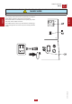
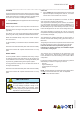
The following is a simplied diagram of the fuel feed circuit.
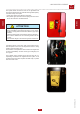
IMPORTANT: before the threading, to se-
cure the seal of the pipe tting, apply an
ANAEROBIC GLUE (like IDEALBLOCK)
on the shrew thread.
Pipe tting ø 20: connection for
the refuelling from an outside tank
Sheaths for connec-
tion of the pump and
fuel return from the
tank which is tted
on the edge of the
machine
Outside tank
Tank on the edge of the machine
Sheath ½": connection for fuel transfer pump
Sheath 1": connection of the pipe for the fuel
return to an outside tank
Fuel level gauge. The level gauge has to connected to the PCB
control transfer pump (see the specic electric diagram)
Caps to remove
(when forecast)
M
29.1.1
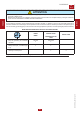
SELF-LOADING PREARRANGEMENT
REV.0-06/10
!
The purpose of this diagram is only to provide guidance.
The design and implementation of the entire system must
be performed by qualied personnel familiar with the speci-
c rules applicable to the installation site.
33