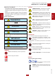
language USE AND MAINTENANCE MANUAL TRANSLATION OF THE ORIGINAL INSTRUCTIONS – ENGLISH “FPT” GE GE GE GE • • • • 165 185 225 275 FSX FSX FSX FSX Gruppo Elettrogeno Generating Set Groupe Electrogene Grupos Electrógenos M A D E • • • • Stromerzeuger • Skupina generátoru Grupo Gerador Генераторная Установка Stroomaggregaten I N I T A L Y Codice Code Code Codigo Kodezahl Código Код Code Kód CJ3K70E19003 Edizione Edition Édition Edición Ausgabe Edição Издание Editie Edice 11.
REV.0-12/16 INDEX . M1.1 M1.4 M2 M2.1 M2.5 INTRODUCTION....................................................................................................................... PAG. CE MARK................................................................................................................................. PAG. SYMBOLS AND SAFETY PRECAUTIONS.................................................................................... PAG. WARNINGS..........................................................
The Manufacturer shall not be liable for ANY USE OF THE PRODUCT OTHER THAN THAT PRECISELY SPECIFIED IN THIS MANUAL and is thus not liable for any risks which may occur as a result of IMPROPER USE. The Company does not assume any liability for any damage to persons, animals or property. Our products are made in conformity with the safety norms in force, for which it is advisable to use all these devices or information so that the use does not bring damage to persons or things.
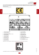
M 1.4 REV.7-02/14 CE MARKING GENERATING SETS ENGLISH ENGLISH Any of our product is labelled with CE marking attesting its conformity to appliable directives and also the fulfillment of safety requirements of the product itself; the list of these directives is part of the declaration of conformity included in any machine standard equipment. Here below the adopted symbol: CE marking is clearly readable and unerasable and it can be either part of the data-plate.
DANGER - The symbols used in this manual are designed to call your attention to important aspects of the operation of the machine as well as potential hazards and dangers for persons and things. Moreover, this symbolism intends to draw your attention with the aim to give you indications for a correct use and, as a result, to obtain a good operation of the machine or equipment used. ! HIGH VOLTAGE - Attention High Voltage.There can be parts in voltage, dangerous to touch.
FIRST AID. In case the operator shold be sprayed by accident, from corrosive liquids a/o hot toxic gas or whatever event which may cause serious injuries or death, predispose the first aid in accordance with the ruling labour accident standards or of local instructions.
• Do not replace the tires with types different from the original ones. • Check that the brakes and the optical signaling of the trailer are working properly. • Verify that the bolts of the wheels are in place and well tightened. • Do not park the machine (on trailer or site tow) on a steep slope. For the stops, not followed by a work session, always engage the parking brake and / or block the wheels by means of wheel chocks. • Do not tow the trailer on bumpy roads.
ADDITIONAL PRECAUTIONS FOR LIGHTING TOWERS ! ATTENTION The lighting towers is designed to be used with a generating set or with a fixed mass on its base. The weight and positioning of the generating set on the base are essential for the safety of the lighting tower. Failure to comply with this provision causes a serious danger of tipping or instability during operation and during handling with site tow If necessary, contact the service.
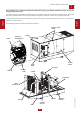
M 0 REV.0-12/16 DESCRIPTION OF THE MACHINE The generating set is a unit which transforms the mechanical energy, generated by endothermic engine, into electric energy, through an alternator. The bunded base must ensure the containment of fluids in the engine and fuel tank in the event of any loss, to prevent their dispersion in the environment. ENGLISH The recessed control panel houses the sockets and machine.
0.1 REV.1-11/14 RECORDING DATA The manual is for the range of machines indicated on the front cover. With the scope to facilitate the search of the spare parts and maintain information of the bought machine, is necessary to record some data. 1. 2. 3. 4. 5. 6. 7. 8. Model of machine Serial number of the machine Serial number of the engine Name of the dealer where bought the machine Address of the dealer Phone number of the dealer Date of the bought machine Notes ENGLISH RECORDING DATA 1. 2. 3. 4. 5.
! M 3 REV.1-02/04 MACHINE UNPACKING NOTE + Be sure that the lifting devices are: correctly mounted, ENGLISH ENGLISH adequate for the weight of the machine with it’s packaging, and conforms to local rules and regulations. When receiving the goods make sure that the product has not suffered damage during the transport, that there has not been rough handling or taking away of parts contained inside the packing or in the set.
GENERAL PRECAUTIONS WHEN HANDLING THE MACHINE. MOVING METHOD The generating sets are lifted with different methods according to the unit’s configuration. Below are the main methods of moving/lifting the genset. ! MOVING THE GENERATING SET VIA FORKLIFT When lifting with a forklift it is necessary to fork the baseframe sideways so that the forks stick out from one side to the other side, widening them to distribute the weight properly, maintaining the genset level.
M 4.2.1 REV.0-06/10 TRANSPORT AND HANDLING ENGLISH ENGLISH MOVING THE GENERATING SET VIA CABLES OR CHAINS OK MOVING BY SITE TROLLEY / TRAILER ! use should be respected. BEWARE DO NOT TOW the generating set without trailer, be it manually or using a vehicle. SITE TOW CTL: this trailer is made by the manufacturer and connected to the generating set baseframe, it can not be towed on public roads. Therefore it can only be used on private roads and no through traffic zones.
30/07/12 CJ3K70E1_IT M 2.7 REV.
ENVIRONMENTAL CONDITIONS ATTENTION ATTENTION ! Open gensets (SKID) have to be located in an area protected from rain, snow, high humidity and direct exposure to the sun. Rain or high humidity on GE genset alternator, in particular during operation, cause an increase in voltage output, winding faults, electric discharge towards ground, with damage to the genset and injury to persons. Dust, in particular saline dust, must be avoided.
FIXED OUTDOOR INSTALLATION If a shelter is used to protect the genset (see figure), it should NOT be attached to it. Even if a shelter is temporary the below indications should be followed: SAFE DISTANCE ! A safe distance has to be kept between genset and fuel deposits, inflammable goods (cloths, paper, etc.), chemicals, according to indications provided by the authority in charge.
Floor should be levelled and suitable to sustain genset weight. Thresholds on doors and openings should have a barrier in order to avoid liquids leaking. In case it is not possible to provide a door with a barrier, the genset should have a collection base appropriate for the quantity of liquid it contains, in any case dimensions of collection base must be in accordance to the laws in force in country of installation. Sample of outdoor installation with shelter H=ALTEZZA G.E. H=HEIGTH G.S. H=HAUTEUR G.E.
Electro ventilator capacity can be calculated as follows: Fan Capacity [m3/h]= Transmitted heat [Kcal/h] 0,287 x ∆t [°C] Considering: ENGLISH • heat to radiation is indicated on engine/alternator technical data sheet; • 0. 287 is specific heat for each m3 of air at 20°C; • Δt in °C is usually considered as equal to 5 °C (worst conditions are considered).
M 20 REV.2-04/15 SET-UP FOR OPERATION (DIESEL ENGINE) WATER COOLED SYSTEMS FUEL The starter battery is supplied already charged and ready for use. Before starting the gen-set connect the cable + (positive) to the pole + of the battery, by properly tightening the clamp. In case of models with warning light: check the state of the battery by means of the indicator placed in the upper part.
COOLING LIQUID ELECTRICAL CONNECTIONS ATTENTION ! A qualified electrician should carry out electrical connections according to the norms in force. Do not remove the radiator tap with the motor in operation or still hot, as the liquid coolant may spurt out and cause serious burns. Remove the tap very carefully. ENGLISH The electrical connection to the User system is a very important operation: safety and good operation of the genset and User system depend on a correct electrical connection.
REV.0-12/16 STARTING AND STOPPING START-UP PANELS ! NOTE ENGLISH Do not alter the primary conditions of regulation and do not touch the sealed parts. START-UP FROM CONTROL UNIT EP6 To start-up from control unit EP6, see the manual attached. START-UP FROM CONTROL UNIT AMF25 To start-up from control unit AMF25, see the manual attached. START-UP FROM PARALLEL CONTROL UNIT To start-up from parallel control unit, see the manual attached.
The protection against electric shock from contact indirect is ensured by the “electrical separation” with equipotential bonding between all the exposed conductive parts of the generating set. Machines equipped with insulation resistance monitor allow intentionally not to connect the ground terminal PE (12) to an earthing system. Located on the front of the machine the insulation resistance monitor has the function of continuously monitoring the ground insulation of live parts.
REV.0-12/16 COMANDI - CONTROLS - COMMANDES - MANDOS - BEDIENELEMENTE - COMANDOS СИСТЕМЫ УПРАВЛЕНИЯ - BEDIENING M 31 B6 L5 Z2 Z9 A3 (SR) T5 (SR) R3 N2 Z2 N2 Z2 E7 (SR) S7 (SR) 15 N2 15 B3 X1 15 KIT 6 PRESE 6 SOCKETS KIT * Solo per versione con Quadro Automatico | Only for Automatic transfer unit version R3 S7 T5 X1 Z2 Z9 Descrizione Presa di corrente in c.a.
Description Function Z2 Thermal-magnetic circuit breaker General switch for the gen-set. It protects both gen-set and related electrical circuit from over current /short circuit. Z9 Engine control unit AMF25 Engine control unit. Genset stop/ start. Handling of generator alarms. On-screen display of alarms, measurements, operating messages. B6 Controller power switch Turns the generator control board on and off.
! OPERATING CONDITIONS WARNING WARNING + During the use of the electricity-generating group NEVER EXCEED the power indications, paying careful attention when several loads are powered simultaneously. For the canopy generator sets provided with doors, the following instruction shall be observed. During the normal operation, the doors of the engine compartment and/or the electrical box shall be kept closed, locked up if possible, as they must be considered in all respects as protection barriers.
SINGLE-PHASE LOADS Power to monophase utilities by means of three-phase generators requires some operating limitations. - In single-phase operation, the declared voltage tolerance can no longer be maintained by the regulator (compound or electronic regulator), since the system becomes highly unbalanced. The voltage variation on the phases not affected by the power can prove dangerous; we recommend sectioning the other loads eventually connected.
USAGE WITH EAS AUTOMATIC START-UP PANEL The electricity-generating group in combination with the EAS automatic start-up panel forms a unit for distributing electrical energy within a few seconds of a power failure from the commercial electrical power line. Below is some general operating information; refer to the automatic panel’s specific manual for details on installation, command, control and signalling operations. Perform connections on the installation in safety conditions.
LEGEND: NOTE D1 D2 D3 THE SETTING MODIFICATIONS OF GFI ARE EXECUTED BY QUALIFIED PERSONNEL. IN CASE, CONTACT AFTER SALES SUPPORT. BEFORE USING THE MACHINE CHECK THE ON WARNING LAMP LIGHTING. D4 D5 D6 D7 D8 The relay allows to select the tripping current value so as to keep values of contact voltage of the limits indicated by the electrical security norms.
! NOTE USE AS TROUBLE INDICATOR: Placed on the front panel, the insulation monitor (A3) is a device which controls continuously the insulation of the generation a.c. circuits towards the ground. ENGLISH LEGEND: 1. Adjustment of Alarm threshold 2. Set-alarm dip-switches 3. Led, pre-allarm indication 4. Led , power indication 5. Led Alarm indication 6. Test push-button 7. Reset push-button 8. Adjustment of- PRE-ALARM threshold DO NOT INTERVENE ON THE SETTING OF THE PROTECTION SWITCH.
M 29.2 REV.0-07/10 3-WAY VALVE FUEL SYSTEM KIT ! ENGLISH ATTENTION The fuel conveying, including that from the external tank, is always controlled by the engine fuel pump, so it is recommended to comply with the instructions below to get proper operation: - place the external tank at the same level of the generator ; - the minimum diameter of the connecting hoses must be 15 mm; - the maximum length of the connecting hoses must be 5m.
OPERATION The operating mode is selected by means of a three-position switch Aut-0-Man. Manual Position By turning the manual switch in this position the pump is started. The selector turns back to zero when releasing it. In manual mode, the pump is stopped only when reaching the 3 rd level of the fuel sensor. PUMP UNIT It is usually installed on the generator set already connected to the tank and the control board. It consists of an electric pump and a manual backup pump connected by a series of pipes.
M 29.1.1 REV.0-06/10 SELF-LOADING PREARRANGEMENT The following is a simplified diagram of the fuel feed circuit. The purpose of this diagram is only to provide guidance. The design and implementation of the entire system must be performed by qualified personnel familiar with the specific rules applicable to the installation site. ENGLISH IMPORTANT: before the threading, to secure the seal of the pipe fitting, apply an ANAEROBIC GLUE (like IDEALBLOCK) on the shrew thread.
! M 38.6 REV.1-02/17 REMOTE CONTROL TCM 35 MAKE SURE The coupling of the TCM 35 with the generating set, ready for remot starting, permits to work far from the set itself. The remote control is connected to the front plate (X1), and/or rear plate, with a multiple connector. ENGLISH The TCM35 remote control only works with the controller (generator management and control unit) in AUT mode (automatic mode).
Problem Possible cause M 40.2 REV.3-07/06 TROUBLESHOOTING Solution ENGINE Check position 2) 3) Start-up switch (I6) (where it is assembled) in incor- 1) rect position 2) Emergency button (L5) pressed 3) Preheating (where it is assembled) 4) 5) Engine control unit or starting key faulty. Battery low 4) 5) 6) 7) 8) 9) Battery cable terminals loose or corroded Start-up motor defective No fuel or air in feed circuit Malfunction on feed circuit: defective pump, injector blocked, etc.
Problem Possible cause M 40.2.1 REV.3-07/06 TROUBLESHOOTING Solution GENERATOR 1) 2) 1) 2) Voltage switch in position 0 Voltage switch faulty 3) 4) 3) Protection tripped due to overload Differential protection device tripped.
MOVING PARTS can injure ATTENTION • Have qualified personnel do maintenance and troubleshooting work. • Stop the engine before doing any work inside the machine. If for any reason the machine must be operated while working inside, pay attention moving parts, hot parts (exhaust manifold and muffler, etc.) electrical parts which may be unprotected when the machine is open • Remove guards only when necessary to perform maintenance, and replace them when the maintenance requiring their removal is complete.
IMPORTANT ! The information given in the table is only indicative. Specific instructions are given in the operation manuals. The engine and alternator manufacturers indicate specific maintenance and control intervals: it is obligatory to consult the books, OPERATION AND MAINTENANCE of the engine and alternator provided with the generator you are using. If such documents are not supplied with the generator set, ask for a copy to the customer service.
! M 43.2 REV.0-09/05 MAINTENANCE ATTENTION ENGLISH For the electricity-generating groups prearranged for automatic operation, in addition to carrying out all periodic maintenance operations foreseen for normal usage, various operations must be carried out that are necessary in relation to the specific type of use. The electricity-generating group in fact must be continuously prepared for operation, even after prolonged periods of inactivity.
CUST OFF In case the machine should not be used for more than 30 days, make sure that the room in which it is stored presents a suitable shelter from heat sources, weather changes or anything which can cause rust, corrosion or damages to the machine. + As cust off we intend all operations to be made, at utilizer’s care, at the end of the use of the machine.
FPT (IVECO) NEF67 TE1F Stage 3A Diesel 4-Stroke / Water 6/ 6700 cm³ 145 kW (197.2 HP) 131.5 kW (178.8 HP) 105 kW (143 hp) 1500 rpm 26.5 l/h 25.5 l 12 l Electric 12V - 180Ah 425 l 16 h IP 44 3750x1400x2030 2700 kg 93 dB(A) (68 dB(A) @ 7 m) 94 dB(A) (69 dB(A) @ 7 m) 2000 / 14 / CE * Dimensions and weight are inclusive of all parts OUTPUT Output powers according to ISO 8528-1 (temperature 40°C, 30% relative humidity, altitude 1000 m above sea level). Stand-by power (LTP): emergency power.
FPT (IVECO) NEF67 TM4 Diesel 4-Stroke / Water 6/ 6700 cm³ 165 kW (224 HP) 150 kW (204 HP) 119 kW (162 hp) 1500 rpm 29.4 l/h 25.5 l 12 l Electric 12V - 180Ah 425 l 15.5 h IP 44 3750x1400x2030 2800 kg 93 dB(A) (68 dB(A) @ 7 m) 94 dB(A) (69 dB(A) @ 7 m) 2000 / 14 / CE * Dimensions and weight are inclusive of all parts OUTPUT Output powers according to ISO 8528-1 (temperature 40°C, 30% relative humidity, altitude 1000 m above sea level). Stand-by power (LTP): emergency power.
Type / Cooling system Cylinder / Displacement Stand by net power PRP net power COP net power Speed Fuel consumption (75% of PRP) Cooling system capacity Engine oil capacity Starter GENERAL SPECIFICATIONS Battery Tank capacity Running time (75% of PRP) Protection *Dimensions / max. on base Lxwxh *Weight on base Measured acoustic power Lwa (pressure LpA) Garanteed acoustic power Lwa (pressure LpA) FPT (IVECO) N67 TEM7 194 kW (264 hp) 176.5 kW (240 hp) 141.5 kW (192.5 hp) 37.3 lit.
Type / Cooling system Cylinder / Displacement Stand by net power PRP net power COP net power Speed Fuel consumption (75% of PRP) Cooling system capacity Engine oil capacity Starter GENERAL SPECIFICATIONS Battery Tank capacity Running time (75% of PRP) Protection *Dimensions / max. on base Lxwxh *Weight on base Measured acoustic power Lwa (pressure LpA) Garanteed acoustic power Lwa (pressure LpA) FPT (IVECO) C87 TE3 249 kW (338 hp) 229 kW (311 hp) 178 kW (242 hp) 44.5 lit.
1880 131 M 2.7.1 REV.
ENGLISH E3 F3 G3 H3 I3 L3 M3 N3 O3 P3 Q3 R3 S3 T3 U3 V3 Z3 W3 X3 Y3 A4 B4 C4 D4 E4 F4 G4 H4 I4 L4 M4 N4 O4 P4 Q4 R4 S4 T4 U4 V4 Z4 W4 X4 Y4 A5 B5 C5 D5 E5 F5 G5 H5 I5 L5 M5 N5 O5 P5 Q5 R5 S5 T5 U5 V5 Z5 W5 X5 Y5 A6 B6 C6 D6 E6 F6 G6 H6 : Open circuit voltage switch : Stop push-button : Ignition coil : Spark plug : Range switch : Oil shut-down button : Battery charge diode : Relay : Resistor : Sparkler reactor : Output power unit : Electric siren : E.P.4 engine protection : Engine control PCB : R.P.M.
H 47 S5 F R1 M - 1 30A F1 8A F2 + 1 1 3 3 4 9 (87a) avv. K1 B6 10 10 B+ 7 T1 D+ 1 10 15 (87) (30) U1 7 7 3 10 D+ W (87a) stop K2 16 (87) Z1 5 5 5 (30) 3 Togliere cavallotto tra i morsetti per poter inserire i pulsanti di emergenza esterni. Remove jumper from terminals to connect the external emergency button. BIxxx - Ingresso da configurare in base agli optional richiesti. BIxxx - Input to be configured according required options.
02/12/16 CL9D00E1_IT J2-...... Y8 EDC7 - UC31 + 15 J3-6 +BATT J7-3 10A J7-4 START COMMAND 7 + X8 - 25 S 9 5 J2-10 12 J2-8 16 KEY ON (+15) (D) + A9 - 27 S 2 J2-19 11 17 18 H1 OPTIONAL: KIT PROTEZIONE BASSO LIV. ACQUA RADIATORE (B) (C) J3-9 HIGH WATER TEMP. SWITCH 19 Q5 J7-1 J2-5 GROUND 2 J2-17 WATER TEMP. SENDER J3-2 J2-4 Esp. Exp. T P B9 16 12 20 OIL PRESS. SENDER 13 P5 L1 J3-4 J2-31 WATER IN FUEL SENDER J3-10 J2-9 4 3 J7-5 LOW OIL PRESS.
1 1 K1 (87a) avv. B6 7 3 15 (87) (30) (87a) K2 stop 5 (30) 3 16 (87) 10 10 7 B 10 6 3 12 Togliere cavallotto tra i morsetti per poter inserire i pulsanti di emergenza esterni. Remove jumper from terminals to connect the external emergency button. 2 5 Y7 BIxxx - Ingresso da conf igurare in base agli optional richiesti. BIxxx - Input to be configured according required options.
G 3 02/12/16 CL9D00E1_IT A U V W N COM RG SG TG NG 60 S1 U 60 S2 59 L1 59 S1 61 L2 61 U L3 S2 S1 60 63 63 U S2 60 51 51 2A 52 52 55 F3 54 L1 55 56 L3 53 53 2A N 2A 65 65 56 F4 F5 L2 54 BI3 nero/black BI2 BI4 Modifica Modification Denominazione: Denomination: BI6 3 BI7 Alla Pag. To Page Da Pag. From Page 12 3 DER3/0D 2 8 5 6 9 10 11 12 4 Macchina: Machine: 9 E9 A1 U B06 N3 Disegnatore: Designer: 225/275/335/385/455. Balducci F. Aux.
02/12/16 CL9D00E1_IT BI4 BI7 BI6 9 1 nero/black BI3 D6 BI1 40 5 11 40 BI2 42 42 nero/black 6 B05 Esp. Exp. A 12 nero/black 21 24 - GBC K6 CB + 2A F F10 8 78 79 B02 B06 4A F F11 72 9 A1 A2 22 10 68 2A 69 F9 9 70 24 230Vac 21 22 GCB N3 K6 MCB K5 Z9 AMF25 Alla Pag. To Page Da Pag. From Page N Disegnatore: Designer: F Data: Date: 21.06.2016 Macchina: Machine: Balducci F. 19.02.2016 CJ3K70F1.S.023-A Dis. n°: Dwg. n°: CH7K20E1.
02/12/16 CL9D00E1_IT R S T T S R T S R G N N 400V/63A 125A Z2 G T S R T S R 400V/125A N N Esp. Exp. 63A Z2 Id G N2 Alla Pag. To Page Da Pag. From Page Id 32A/0,03A T S R Id 400V/32A Id T S R Id Disegnatore: Designer: H 230V/16A N R Id R Macchina: Machine: Balducci F. Aux. version with sockets (400Tx4/230Mx2) DMT Modifica Modification Denominazione: Denomination: G N2 Id 16A/0,03A T S R Id 400V/16A Id T S R 20.07.
02/12/16 CL9D00E1_IT F 51 51 54 2A L1 54 N 65 65 BI4 Esp. Exp. BI5 12 4 65 9 65 8 7 2 1 Alla Pag. To Page Da Pag. From Page A2 A1 19.01.2016 Data: Date: 3 iso K4 N3 Macchina: Machine: Dis. n°: Dwg. n°: Balducci F. CH7K20E1.S.025 84306.prg Z2 U5 Disegnatore: Designer: RG SG TG NG B07 Electrical diagram for Isometer vers.
30/07/12 CJ3K70E1_IT D7 1 2 INGRESSO LIVELLI LEVEL INPUT SUPPLY DC 12-24Vdc ALIMENTAZIONE nero/black (2) 3 30 39 PIENO FULL 38 VUOTO EMPTY 40 38 39 40 11 12 13 14 15 16 MARR. A8 EV MAX = 1A TROPPO PIENO TOO FULL 17 A Esp. Exp. 19 20 86 21 B Alla Pag. To Page Da Pag. From Page 65 51 Macchina: Machine: 5 5 FM SX Balducci F. Disegnatore: Designer: 07.06.2010 Data: Date: Data Da t e Progetto: Project: 8 4 3 0 6 .p rg 84306.S.015-A Dis. n°: Dwg. n°: 2 0 .1 0 .