
User Manual

ASSEMBLY
CTL400
M
6.2
REV.0-06/00
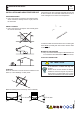
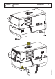
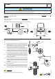
Nota: Lift the machine and assemble the parts as shown in the drawing
For assembling the generating set on the trolley CTL400
please keep to following instructions:
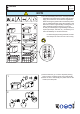
1) - Lift the generating set (by means of suitable hook).
2) - Slightly x the jaw (3) of the parking foot to the bar
with the M10x20 screws, the M10 nuts and the wa-
shers (so as to let the foot sprag go through.
3) - Split (unscrewing them) the two parts of the foot
(4S-4I) to be able later to assemble them on the jaw.
4) - Introduce into the jaw (3) the upper part (4S) of the
foot and screw again the lower part (4I), then tighten
the screws (4V) of the jaw to the towbar and block
momentaneously with the lever (4L) the whole foot.
5) - Assemble on the machine the towbar (5) complete
of foot with the M10x20 screws, nuts and washers
(see g. page M6.2).
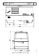
6) - Assemble the axle (7) to the base of the machine
(see g. page M6.2) with the M 10x20 screws and
relative washers (two per part) so that their supports
coincide.
8) - Insert the wheel (9) on the axle then screw the self
blocking nuts (8).
9) - Pump the tyre (9) bringing the pressure to four atms.
10) - Lower the machine to the ground and place the par-
king foot denitively (regulating at the best height).
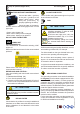
ATTENTION
Do not substitute the original tires with other types.
!
4
5
3
4S
4I
4L
4V
7
8
9
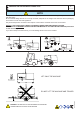
TRAILERS
The machines provided for assembling the CTL accessory (slow towing trolley) can be towed up to a maximum speed of 40
Kms/hour on asphalted surfaces.
Towing on public roads or turnpikes of any type IS EXCLUDED, because not in possesion of the requirements by national and
foreign trafc norms.
10/06/00 M6GB
ATTENTION
The CTL accessory cannot be removed from the machine and used separately (actioned manually or following vehicles) for
the transport of loads or anyway for used different from the machine movements.
!