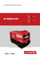
USE AND MAINTENANCE MANUAL GE 20000 KS/GS M A D E I N I T A L Y Codice Code Codigo Kodezahl 250309003 Edizione Edition Edición Ausgabe 06.
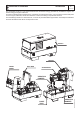
DESCRIPTION OF THE MACHINE GE 20000 KS/GS M 0 REV.0-06/14 The generating set GE is a unit which transforms the mechanical energy, generated by endothermic engine, into electric energy, through an alternator. Is meant for industrial and professional use, powered by an endothermic engine; it is composed of various main parts such as: engine, alternator, electric and electronic controls, the fairing or a protective structure.
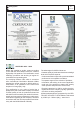
M Quality system 01 REV.4-03/12 UNI EN ISO 9001 : 2008 The certifying institute, ICIM, which is a member ofthe International Certification Network IQNet, awarded the official approval to MOSA after anexamination of its operations at the head office andplant in Cusago (MI), Italy.
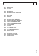
M 1 INDEX REV.3-04/14 QUALITY SYSTEM COPYRIGHT NOTES CE MARK DECLARATION OF CONFORMITY TECHNICAL DATA TECHNICAL DATA ENGINE DRIVEN WELDER ADVICE SYMBOLS AND SAFETY PRECAUTIONS INSTALLATIONS AND ADVICE INSTALLATION DIMENSIONS PACKING TRANSPORT AND DISPLACEMENTS ASSEMBLY: CT........
M 1.01 Copyright REV.0-10/02 ! ATTENTION This use and maintenance manual is an important part of the machines in question. The assistance and maintenance personel must keep said manual at disposal, as well as that for the engine and alternator (if the machine is synchronous) and all other documentation about the machine. We advise you to pay attention to the pages concerning the security (see page M1.1). All rights are reserved to said Company. It is a property logo of MOSA division of B.C.S. S.p.
Notes M 1-1 REV.1-03/14 INFORMATION Dear Customer, We wish to thank you for having bought a high quality set. Our sections for Technical Service and Spare Parts will work at best to help you if it were necessary. To this purpose we advise you, for all control and overhaul operations, to turn to the nearest authorized Service Centre, where you will obtain a prompt and specialized intervention.
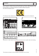
M 1.4 CE MARKING REV.7-02/14 Any of our product is labelled with CE marking attesting its conformity to appliable directives and also the fulfillment of safety requirements of the product itself; the list of these directives is part of the declaration of conformity included in any machine standard equipment. Here below the adopted symbol: CE marking is clearly readable and unerasable and it can be either part of the data-plate. TYPE SERIAL N° Made in UE-ITALY TYPE/N° VOLTAGE(V) POWER(W) Hz G P.F.
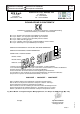
I GB F Dichiarazione conformità Declaration of conformity Déclaration de conformité Konformitätserklärung Declaración de conformidad Declaração de conformidade BCS S.p.A. M 1.4.1 REV.2-10/13 Stabilimento di Cusago, 20090 (Mi) - Italia V.le Europa 59 Tel.
Technical data GE 20000 KS/GS M 1.5 REV.0-06/14 Technical data GENERATOR Stand-by three-phase power PRP three-phase power PRP single-phase power Insulating class ALTERNATOR Type Frequency ENGINE Mark / Model Type / Cooling system Cylinders / Displacement *Stand-by net output *PRP net output Speed Fuel consumption (75% of PRP) Engine oil capacity Starter GENERAL SPECIFICATIONS Tank capacity Running time (75% of PRP) Protection *Dimensions / max.
M 2 WARNINGS REV.1-02/14 The installation and general warnings regarding operations are aimed achieving correct use of the machine and/or apparatus in the place where it is used as a genset and/or motor welder. - Advice to the User about the safety: + NB: The information contained in the manual can be changed without notice. Any damage caused in connection with the use of these instructions shall not be considered as they are only indicative.
M 2-1 SYMBOLS AND SAFETY PRECAUTIONS REV.2-06/10 STOP - Read absolutely and be duly attentive Read and pay due attention ! GENERAL ADVICE - If the advice is not respected damage can happen to persons or things. HIGH VOLTAGE - Attention High Voltage. There can be parts in voltage, dangerous to touch. The non observance of the advice implies life danger. FIRE - Danger of flame or fire. If the advice is not respected fires can happen. HEAT - Hot surfaces.
M 2.6 INSTALLATION AND ADVICE REV.1-06/07 INSTALLATION AND ADVICE BEFORE USE GASOLINE ENGINES + Use in open space, air swept or vent exhaust gases, which contain the deathly carbone oxyde, far from the work area. Check that the air gets changed completely and the hot air sent out does not come back inside the set so as to cause a dangerous increase of the temperature. 1,5 m DIESEL ENGINES + Use in open space, air swept or vent exhaust gases far from the work area.
D E NL Luftzirkulation Instalación GE 20000 KS/GS GE 10 KSX M 2.7 REV.
D E NL Abmessungen Dimensiones GE 20000 KS/GS GE 10 KSX M 2.7.1 REV.
M 3 UNPACKING REV.1-02/04 NOTE ! + Be sure that the lifting devices are: correctly mounted, adequate for the weight of the machine with it’s packaging, and conforms to local rules and regulations. When receiving the goods make sure that the product has not suffered damage during the transport, that there has not been rough handling or taking away of parts contained inside the packing or in the set. In case you find damages, rough handling or absence of parts (envelopes, manuals, etc.
M 4 TRANSPORT AND DISPLACEMENTS COVERED UNITS REV.1-06/10 ! NOTE Transportation must always take place with the engine off, electrical cables and starting battery disconnected and fuel tank empty. Be sure that the lifting devices are: correctly mounted, adequate for the weight of the machine with it’s packaging, and conform to local rules and regulations. Only authorized persons involved in the transport of the machine should be in the area of movement.
M 6.2 CTL400 ASSEMBLY REV.0-06/00 ! ATTENTION The CTL accessory cannot be removed from the machine and used separately (actioned manually or following vehicles) for the transport of loads or anyway for used different from the machine movements. TRAILERS The machines provided for assembling the CTL accessory (slow towing trolley) can be towed up to a maximum speed of 40 Kms/hour on asphalted surfaces.
I GB F Set-up for operation (Engine diesel) Air cooled systems M 20 REV.1-09/05 OIL BATH AIR FILTER BATTERY WITHOUT MAINTENANCE Connect the cable + (positive) to the pole + (positive) of the battery (after having taken away the protection), by properly tightening the clamp. Check the state of the battery from the colour of the warning light which is in the upper part. - Green colour: battery OK - Black colour: battery to be recharged - White colour: battery to be replaced DO NOT OPEN THE BATTERY.
M 21 ENGINE STARTING AND USE (DIESEL ENGINES) REV.0-06/99 Check daily ENGINES WITHOUT ACCELERATOR LEVER lnsert the electric protection device (D-Z2-N2) lever towards above and, where mounted, check the isolation monitor (A3) see page M37 – NOTE ! Do not alter the primary conditions of regulation and do not touch the sealed parts. ENGINES WITH MANUAL RECOIL Hold the starting handle firmly. OFF ON START Introduce the key (Q1), turn it clockwise completely, leaving it as soon as the engine starts.
M 21.1 ENGINE STARTING AND USE (DIESEL ENGINES) REV.0-06/99 ENGINE WITH PREHEATING GLOW PLUGS Turn the starter key (Q1) on the position "preheating glow plugs" (the glow plugs light will be on I4), when the light is off, turn the starter key completely clockwise until the engine begins to fire. Let the engine run for some minutes before drawing the lood. ENGINES WITH R.P.M. ELECTRONIC ADJUSTER (ONLY FOR GENERATING SET) Turn the starter key (Q1) completely clockwise until the engine begins to fire.
M 22 STOPPING THE ENGINE (DIESEL ENGINE) REV.0-10/00 Before stopping the engine it is compulsory to effect the following operations: - stop to draw three/single-phase current from the auxiliary sockets. OFF ON START Remove the key (Q1) turning it counter clockwise, OFF position, then take it out. NB.: for safety reason the key must be kept by qualified personel. ENGINES WITH R.P.M. ELECTRONIC ADJUSTER (ONLY FOR GENERATING SET) - stop to draw power from the welding sockets (only for TS models).
4A 9 10 12 15 16 17 19 22 23 24 24A 24B 25 26 27 28 29 30 31 31A 31B 31C 32 33 34 34A 35 36 37 42 42A 47 49 54 55 55A 56 59 59A 59B 59C 59D 59E 59F 63 66 67A 68 69A 70 71 72 73 74 75 76 79 86 86A 87 88 A3 A4 B2 B3 M 30 CONTROLS LEGENDE REV.3-04/13 Hydraulic oil level light Welding socket ( + ) Welding socket ( - ) Earth terminal A.C. socket Accelerator lever Feed pump 48V D.C.
Comandi Controls Commandes GE 20000 KS/GS M 31 REV.
M 37 Using the generator REV.3-11/11 ! WARNING It is absolutely forbidden to connect the unit to the public mains and/or another electrical power source . Access forbidden to area adjacent to electricity-generating group for all nonauthorized personnel. ! WARNING For the canopy generator sets provided with doors, the following instruction shall be observed.
M 37.1 Using the generator The frequency, and therefore the number of motor revolutions, is maintained constant by the motor’s speed regulation system. Generally, this regulator is of a mechanical type and presents a droop from no-load to nominal load which is less than 5 % (static or droop), while under static conditions precision is maintained within ±1%.Therefore, for generators at 50Hz the no-load frequency can be 52–52.5 Hz, while for generators at 60Hz the no-load frequency can be 62.5-63Hz.
I GB F M 37.2 Using the generator REV.1-09/05 DIFFERENTIAL SWITCH The differential switch or differential relay guarantee protection against indirect contacts due to malfunction currents towards the ground. When the device detects a malfunction current that is higher than the nominal current RESET or the set current, it intervenes by cutting off power to the circuit connected. In the case of an intervention A 1a0 M tx10 1 b 0 tx1 I° x1 x10 1c0 1d0 x0.1I° T5.10 T5.9 T5.3 RESET T5.
M 38.5.1 TCM 22 - 40 REMOTE CONTROL REV.1-02/03 ! MAKE SURE When the TCM 22-40 is used, it is not possible to connect the E.A.S automatic intervention unit. The selector LOCAL START/REMOTE START (I6) of the generating set must be switched on REMOTE START. USE OF THE REMOTE CONTROL TCM 22 The coupling of the TCM 22 with the generating set, ready for remot starting, permits to work far from the set itself.
USE OF THE PROTECTION ENGINE PROTECTION ES - EV M 39.4 REV..1-04/03 ENGINE PROTECTION (ES - EV) The devices ES or EV ensure the protection of the engine in case of low oil pressure or engine high temperature.
Diesel engine Troubleshooting M 40.2 REV.3-07/06 Problem The motor does not start up Possible cause Solution ENGINE 1) Start-up switch (I6) (where it is assembled) in 1) Check position incorrect position 2) Emergency button (L5) pressed 2) Unblock 3) Preheating (where it is assembled) 3) Lacking or insufficient preheating phase for sparkplugs. Malfunction in circuit: repair. 4) Engine control unit or starting key faulty. 4) Replace 5) Battery low 5) Recharge or replace.
Troubleshooting Diesel engine M 40.2.1 REV.4-03/11 Problem Possible cause Solution GENERATOR 1) 2) 1) 2) Voltage switch in position 0 Voltage switch faulty 3) 4) 3) Protection tripped due to overload Differential protection device tripped.
M 43 MAINTENANCE REV.1-01/13 ! MOVING PARTS can injure WARNING ●● Have qualified personnel do maintenance and troubleshooting work. ●● Stop the engine before doing any work inside the machine. If for any reason the machine must be operated while working inside, pay attention moving parts, hot parts (exhaust manifold and muffler, etc.) electrical parts which may be unprotected when the machine is open.
M 43.1 MAINTENANCE REV.0-09/05 ! l l ATTENTION Maintenance operations on the electricity-generating group prearranged for automatic operation must be carried out with the panel in RESET mode. Maintenance operations on the installation’s electrical panels must be carried out in complete safety by cutting off all external power sources: ELECTRICAL POWER, GROUP and BATTERY.
I GB F M 45 STORAGE REV.0-06/07 In case the machine should not be used for more than 30 days, make sure that the room in which it is stored presents a suitable shelter from heat sources, weather changes or anything which can cause rust, corrosion or damages to the machine. + Have qualified personnel prepare the machine for storage. GASOLINE ENGINE Start the engine: lt will run until it stops due to the lack of fuel. Drain the oil from the engine sump and fill it with new oil (see page M25).
I GB F + M 46 CUST OFF REV.0-06/07 Have qualified personnel disassemble the machine and dispose of the parts, including the oil, fuel, etc., in a correct manner when it is to be taken out of service. As cust off we intend all operations to be made, at utilizer’s care, at the end of the use of the machine.
A B C D E F G H I L M N P Q R S T U V Z X W Y A1 B1 C1 D1 E1 F1 G1 H1 I1 L1 M1 N1 O1 P1 Q1 R1 S1 T1 U1 V1 Z1 W1 X1 Y1 A2 B2 C2 D2 E2 F2 G2 H2 I2 L2 M2 N2 O2 P2 Q2 R2 S2 T2 U2 V2 Z2 W2 X2 Y2 A3 B3 C3 D3 M 60 ELECTRICAL SYSTEM LEGENDE : Alternator : Wire connection unit : Capacitor : G.F.I.
Stromlaufplan Esquema eléctrico GE 20000 KS/GS M 61.1 REV.
Stromlaufplan Esquema eléctrico GE 20000 KS/GS M 61.2 REV.
Stromlaufplan Esquema eléctrico GE 20000 KS/GS M 61.3 REV.
WWW.MOSA.IT MOSA div. della BCS S.p.A. Stabilimento di Viale Europa, 59 20090 Cusago (MI) Italia Tel. + 39 - 0290352.