language USE AND MAINTENANCE MANUAL TRANSLATION OF THE ORIGINAL INSTRUCTIONS – ENGLISH TS 405 EVO MULTI4 • • • • Motosaldatrice • Schweißaggregat Engine Driven Welder • Motosoldadora Motosoudeuse • По Вышкам Motosoldadoras M A D E I N I T A L Y Codice Code Code Codigo Kodezahl Código Код C1KS10219003 Edizione Edition Édition Edición Ausgabe Edição Издание 08.
REV.0-08/21 INDEX M1.1 M1.4.2 M2 M2.1 M2.5... INTRODUCTION.................................................................................................................. PAG. CE MARK............................................................................................................................ PAG. SYMBOLS AND SAFETY PRECAUTIONS............................................................................... PAG. WARNINGS.......................................................................
The Manufacturer shall not be liable for ANY USE OF THE PRODUCT OTHER THAN THAT PRECISELY SPECIFIED IN THIS MANUAL and is thus not liable for any risks which may occur as a result of IMPROPER USE. The Company does not assume any liability for any damage to persons, animals or property. Our products are made in conformity with the safety norms in force, for which it is advisable to use all these devices or information so that the use does not bring damage to persons or things.
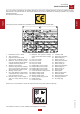
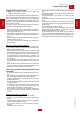
M 1.4.2 REV.7-02/18 CE MARKING ENGINE DRIVEN WELDER ENGLISH CE marking is clearly readable and unerasable and it can be either part of the data-plate. 1 5 6 7 10 8 9 6 15 28 1. 2. 3. 4. 5. Manufacturer name or brand Year of production Engine Driven Welder model Serial number | registration number Reference to the standard confirming that the Engine Driven Welder complies with its requirements 6. Welding process symbol 7.
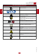
DANGER - The symbols used in this manual are designed to call your attention to important aspects of the operation of the machine as well as potential hazards and dangers for persons and things. Moreover, this symbolism intends to draw your attention with the aim to give you indications for a correct use and, as a result, to obtain a good operation of the machine or equipment used. ! HIGH VOLTAGE - Attention High Voltage.There can be parts in voltage, dangerous to touch.
FIRST AID. In case the operator shold be sprayed by accident, from corrosive liquids a/o hot toxic gas or whatever event which may cause serious injuries or death, predispose the first aid in accordance with the ruling labour accident standards or of local instructions.
• Do not replace the tires with types different from the original ones. • Check that the brakes and the optical signaling of the trailer are working properly. • Verify that the bolts of the wheels are in place and well tightened. • Do not park the machine (on trailer or site tow) on a steep slope. For the stops, not followed by a work session, always engage the parking brake and / or block the wheels by means of wheel chocks. • Do not tow the trailer on bumpy roads.
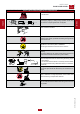
M 2.5.1 REV.0-01/18 SAFETY RULES ENGINE DRIVEN WELDERS SAFETY PRECAUTIONS DURING INSTALLATION AND USE 10° = 20° max 10° 10° Always locate the machine on a flat and solid ground, so as to avoid tipping, slipping or falling during operation. Avoid using the machine on slopes greater than 10 degrees. = 20° max ENGLISH ENGLISH Do not instal equipments closed to heat source, to explosion or fire risk area.
M 2.5.2 REV.0-01/18 SAFETY RULES ENGINE DRIVEN WELDERS SAFETY PRECAUTIONS DURING MAINTENANCE Make use of qualified personnel to carry out maintenance and troubleshooting It is mandatory to stop the engine before performing any maintenance on the machine. ENGLISH ENGLISH Always use protective devices and suitable equipment. Do not touch the engine, the exhaust pipes and the muffler during operation or immediately after.
M 2.5.3 REV.0-01/18 SAFETY RULES ENGINE DRIVEN WELDERS ADDITIONAL REQUIREMENTS FOR ENGINE DRIVEN WELDERS Do not manage electric devices and welding stick whit feet, hands or wet dresses. ENGLISH Protect yourself from electric shock by insulating yourself from work and ground. Use non-flammable, dry insulating material if possible, or use dry rubber amts, dry wood or plywood, or other dry insulating material. Magnetic fields can affect pace-makers.
M 0 REV.0-08/21 DESCRIPTION OF THE MACHINE Unit meant for industrial and professional use. Powered by an endothermic engine; it is composed of various parts such as: engine, alternator, electric and electronic controls, the fairing at a protective structure. The assembling is made on a steel structure, on which are provided elastic support which must damp the vibrations and also eliminate sounds which would produce noise.
0.1 REV.1-11/14 RECORDING DATA The manual is for the range of machines indicated on the front cover. With the scope to facilitate the search of the spare parts and maintain information of the bought machine, is necessary to record some data. 1. 2. 3. 4. 5. 6. 7. 8. Model of machine Serial number of the machine Serial number of the engine Name of the dealer where bought the machine Address of the dealer Phone number of the dealer Date of the bought machine Notes ENGLISH RECORDING DATA 1. 2. 3. 4. 5.
! M 3 REV.1-02/04 MACHINE UNPACKING NOTE + Be sure that the lifting devices are: correctly mounted, ENGLISH ENGLISH adequate for the weight of the machine with it’s packaging, and conforms to local rules and regulations. When receiving the goods make sure that the product has not suffered damage during the transport, that there has not been rough handling or taking away of parts contained inside the packing or in the set.
GENERAL PRECAUTIONS WHEN HANDLING THE MACHINE. MOVING METHOD The generating sets are lifted with different methods according to the unit’s configuration. Below are the main methods of moving/lifting the genset. ! MOVING THE GENERATING SET VIA FORKLIFT When lifting with a forklift it is necessary to fork the baseframe sideways so that the forks stick out from one side to the other side, widening them to distribute the weight properly, maintaining the genset level.
M 4.2.1 REV.1-04/21 TRANSPORT AND HANDLING ENGLISH ENGLISH MOVING THE GENERATING SET VIA CABLES OR CHAINS OK SITE TOW CTL: MOVING BY SITE TROLLEY / TRAILER ! BEWARE DO NOT TOW the generating set without trailer, be it manually or using a vehicle. Trolleys/trailers should only be used to move the generating set for which they were designed. this trailer is made by the manufacturer and connected to the generating set baseframe, it can not be towed on public roads.
21/04/21 C1KS1000_IT M 2.7 REV.0-08/21 INSTALLAZIONE - INSTALLATION - INSTALLATION INSTALACIÓN - LUFTZIRKULATION - INSTALAÇÃO УСТАНОВКА - INSTALLATIE M1.
INSTALLATION AND ADVICE BEFORE USE INSTALLATION Always instal the welder machine on a hard and plan surface in order to avoid rollovers, slips or falls while working; avoid to use the welder machine with slope more than 10°. The operator of the welder is responsible for the security of the people who work with the welder and for those in the vicinity. Particulary remember: - installing operation must be made by authorized and qualified person.
Methods of reducing emissions ENGLISH Maintenance of the arc welding equipment The arc welding equipment should be routinely maintained according to the manufacturer’s recommendations. All access and service doors and covers should be closed and properly fastened when the arc welding equipment is in operation. The arc welding equipment should not be modified in any way, except for those changes and adjustments covered in the manufacturer’s instructions.
COOLING LIQUID The starter battery is supplied already charged and ready for use. Before starting the gen-set connect the cable + (positive) to the pole + of the battery, by properly tightening the clamp. In case of models with warning light: check the state of the battery by means of the indicator placed in the upper part. - Green colour: battery OK - Black colour: battery to be recharged - White colour: battery to be replaced DO NOT OPEN THE BATTERY.
The protection against electric shock from contact indirect is ensured by the “electrical separation” with equipotential bonding between all the exposed conductive parts of the generating set. Machines equipped with insulation resistance monitor allow intentionally not to connect the ground terminal PE (12) to an earthing system. Located on the front of the machine the insulation resistance monitor has the function of continuously monitoring the ground insulation of live parts.
After the starting, keep the engine runs for a few minutes before the energy withdrawal. Check the tab: NOTE Do not alter the primary conditions of regulation and do not touch the sealed parts. TEMPERATURE TIME ≤ - 20° C 5 min. da - 20° C a -10°C 2 min. da - 10° C a -5°C 1 min. ≥ 5° C 20 sec. ENGLISH Start-up at low temperatures. The engine has e good start-up to temperatures of -10°C.
Z2 D 400/230/110V version 59A Z2 D 400/230/48V version AA 59B L5 ENGLISH 15 9 10 X1 T6 12 Z2 D R3 Pos. 9 10 90 Description c.c. welding sockets (+) c.c. welding sockets (-) EVO control Multi 4 X1 T6 AA Remote control socket Wire feeder connector Engine control unit "RGK 420SA" 59A R3 L5 15 D Engine thermal switch Siren Emergency stop button A.C.
ADJUSTING THE WELDING CURRENT This symbol (Norm EN 60974-1 security standards for arc welders ) signifies that the welder can be used in areas with increased risk of electrical shock. ! WARNING ! WARNING It is prohibited for any unauthorized persons to access areas adjacent to the engine driven welder or the welding process.
VRD SWITCH WELDING ARC CONTROL V R D It allows to have the positive or negative welPolarity ding polarity to the electrode holder. It is used specially in the first run with celluloswitch sic electrodes to lower the bath temperature and therefore make welding on low-thickness pipes easier. To carry out the inversion of polarity, the action has given by the switch which is both on the front panel of the welding control and on the remote control.
M 34.2 REV.0-04/21 EXTERNAL BOX POLARITY CHANGE CONNECTION PL 400 BOX PL 400 35% 400 1~50/60 Hz U2(V) 48 60% 360 100% 330 IP 23 Kg 12,5 RCE-PL POLARITY SWITCH 1 2 9 3 8 4 6 5 - Connect the welding cables according to the right polarity. - The welding cables must have an adequate section for the current and the service factor X%. Refer to the DATA PLATE of the PL 400 box - Activate the polarity inversion by acting on the "POLARITY SWITCH" on the BOX PL 400.
M 34.3 REV.0-04/21 WIRE FEEDER CONNECTION ENGLISH ENGLISH TS .... EVO MULTI4 REMOTE CONTROL WIRE FEEDER WIRE FEEDER The adjustment of the welding parameters, voltage and current (wire speed) must be performed directly on the wire feeder. Connect the wire feeder to the welder as explained in the following while the welder is turned off: - Welding cable between the machine’s (9) welding plug (+) and the wire feeder (20m - 50mm2 cable supplied with the WIRE FEEDER).
M 33 REV.0-06/19 WELDING DIGITAL CONTROL EVO MULTI 4 CONTROL WELDING PROCEDURES ENGLISH ENGLISH EVO MULTI4 Figure 1.1: Frontal view of the panel Figure 2.
WELDING SETs MIG/FLUX CORED CONTACT MIG/FLUX CORED CONTACT is a welding procedure that disable the welding voltage until the user does not press the torch button. The type of primary and secondary parameters are the same as the MIG/FLUX CORED mode.
M 33.2 REV.0-06/19 WELDING DIGITAL CONTROL EVO MULTI4 CONTROL ENGLISH ENGLISH TIG LIFT ARC PULSE Figure 2.4: Current at different duty cycles In figure 2.4 it is possible to see that duty cycle does not change the maximum or the minimum current, only the average current. Figure 2.2: Behavior of the current in normal TIG and pulsed It is possible to see in figure 2.6that in PULSED TIG it is possible to reduce the welding cur-rent for a short time.
WELDING SETs There are 3 profiles of welding(Welding Set) for this kind of procedure (pulsed TIG), these are: WS 1 2 3 5 5 5 • SET: This button when pressed shows the machine configuraion parameter, the only parameter so far is the delay of the auto-idle, the default value is 15 seconds. With a medium pressure (3-7 seconds) it will save in the memory the parameter if there was a change. Secondary parameters Current f Duty Delta [A] [Hz] [%] [%] 50 100 150 5.
! WARNING WARNING FREQUENCY The frequency is a parameter that is directly dependent on the motor’s rotation speed. Depending on the type of alternator, 2 or 4 pole, we will have a frequency of 50/60 Hz with a rotation speed of 3000/3600 or 1500/1800 revolutions per minute. The frequency, and therefore the number of motor revolutions, is maintained constant by the motor’s speed regulation system.
ELECTRIC PROTECTIONS + NotE: for some types of alternators (asynchronous alternators) it is not necessary to protect the three-phase output against short circuits and overcurrents, as the asynchronous alternator self-protects itself. The electricity-generating group is protected against short-circuits and against overloads by a thermal-magnetic switch (Z2) situated upstream from the installation. Operating currents, both thermic and magnetic, can be fixed or adjustable in relation to the switch model.
RC2 - RCE REV.0-04/21 REMOTE CONTROL M SERIE EVO / EVO MULTI4 RC2 - RCE - RCE/PL 38.13 RCE/PL POLARITY SWITCH ENGLISH ENGLISH 64 8 8 PUSH AND SCREW TIGHT PUSH AND SCREW TIGHT The remote control for adjusting the welding current or voltage must be connected to the front panel of the machine with a multiple connector. When the remote control is connected to the remote control connector (8), it is functional and automatically excludes the front panel regulation.
7.2 REV.
M 55 REV.0-10/03 RECOMMENDED ELECTRODES (IN ACCORDANCE WITH A.W.S STANDARD) The information here below are to be intended only as indicative since the above norm is much larger. For further details please see the specific norms and/or the manufacturers of the product to be used in the welding process. ENGLISH BASIC ELECTRODES: E 7015 Basic electrrodes wels onlu in d.c. with inverse polarity (+ on the electrode holder) ; there are also types for a.c. Suitable for impure carbon steels.
Problem Possible cause M 40.1 REV.1-01/18 Troubleshooting Solution ENGINE P1 - The motor does not start up 1) Emergency button (L5) pressed 2) Preheating (where it is assembled) ENGLISH 5) Battery cable terminals loose or corroded 6) Start-up motor defective 7) No fuel or air in feed circuit 8) Malfunction on feed circuit: defective pump, injector blocked, etc.
Problem Possible cause M 40.1.1 REV.
Problem Possible cause M 40.1.2 REV.
MOVING PARTS can injure WARNING ● Have qualified personnel do maintenance and troubleshooting work. ● Stop the engine before doing any work inside the machine. If for any reason the machine must be operated while working inside, pay attention moving parts, hot parts (exhaust manifold and muffler, etc.) electrical parts which may be unprotected when the machine is open. ● Remove guards only when necessary to perform maintenance, and replace them when the maintenance requiring their removal is complete.
IMPORTANT ! The information given in the table is only indicative. Specific instructions are given in the operation manuals. The engine and alternator manufacturers indicate specific maintenance and control intervals: it is obligatory to consult the books, OPERATION AND MAINTENANCE of the engine and alternator provided with the generator you are using. If such documents are not supplied with the generator set, ask for a copy to the customer service.
DISASSEMBLE In case the machine should not be used for more than 30 days, make sure that the room in which it is stored presents a suitable shelter from heat sources, weather changes or anything which can cause rust, corrosion or damages to the machine. + Have qualified personnel disassemble the machine and dispose of the parts, including the oil, fuel, etc., in a correct manner when it is to be taken out of service.
KOHLER KDW 1003 Diesel 4-Stroke / water 3 / 1028 cm3 17.2 kW (23.4 HP) 3000 rpm 3.3 l/h 2.4 l Electric 12 Vdc -50Ah 38 l 11.5 h IP 23 1649 x 710x 931 455 Kg 94.7 dB(A) (69.7 dB(A) @ 7 m) 96 dB(A) (71 dB(A) @ 7 m) 2000 / 14 / CE * Dimensions and weight are inclusive of all parts POWER Declared power according to ISO 3046-1 (temperature 25°C, 30% relative humidity, altitude 100 m above sea level). It’s admitted overload of 10% each hour every 12 h.
SMAW (STICK - Coated electrode) 20A / 20.8V ÷ 400A / 20V Continue on 2 scales 20A ÷ 200A / 20A ÷ 400A 330A / 33.2V @ 60% 300A / 32V @ 100% GTAW (TIG - Tungsten electrode) 20A / 10.8V ÷ 400A / 20V Continue on 2 scales 20A ÷ 200A / 20A ÷ 400A 380A / 25.2V @ 35% 330A / 23.2V @ 60% 300A / 22V @ 100% 75 Vcc (79.5 Vcc to peak) < 13 Vcc / Vdc -- Open circuit voltage (no-load voltage) 75 Vcc (79.
CONSTANT VOLTAGE - GMAW WIRE (MIG) - FCAW CORED WIRE (FLUX CORED) 40A / 16V ÷ 400A / 20V Continue 15V - 45V 330A / 30.5V - 60% 300A / 29V - 100% ENGLISH ENGLISH C.V. WELDING (Constant Voltage) Welding current Welding voltage Service M 1.6.1 REV.0-08/21 TECHNICAL DATA OUTPUT CARACTERISTIC C.V.
1115 931 REV.0-08/21 DIMENSIONI - DIMENSIONS - DIMENSIONS M DIMENSIONES - ABMESSUNGEN - DIMENSÕES РАЗМЕРЫ - AFMETINGEN 2.7.
MOSA div. della BCS S.p.A. Viale Europa, 59 20090 Cusago (Milano) Italy Tel.+39 - 0290352.1 Fax +39 - 0290390466 www.mosa.