language USE AND MAINTENANCE MANUAL TRANSLATION OF THE ORIGINAL INSTRUCTIONS – ENGLISH MAGIC WELD 200 • • • • • Schweißaggregat Motosaldatrice Engine Driven Welder • Motosoldadora Motosoudeuse • По Вышкам Motosoldadoras M A D E I N I T A L Y Codice Code Code Codigo Kodezahl Código Код 222509003 Edizione Edition Édition Edición Ausgabe Edição Издание 01.
DESCRIPTION OF THE MACHINE M 0 MAGIC WELD 200 REV.2 - 01/16 The engine driven welder is arranged as a single block composed of the engine and stainless steel box structure where the front is the cover.
M 1 INDEX REV.
M 1.01 Copyright REV.0-10/02 ! ATTENTION This use and maintenance manual is an important part of the machines in question. The assistance and maintenance personel must keep said manual at disposal, as well as that for the engine and alternator (if the machine is synchronous) and all other documentation about the machine. We advise you to pay attention to the pages concerning the security (see page M1.1). All rights are reserved to said Company. It is a property logo of MOSA division of B.C.S. S.p.
Notes M 1-1 REV.1-03/14 INFORMATION Dear Customer, We wish to thank you for having bought a high quality set. Our sections for Technical Service and Spare Parts will work at best to help you if it were necessary. To this purpose we advise you, for all control and overhaul operations, to turn to the nearest authorized Service Centre, where you will obtain a prompt and specialized intervention.
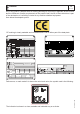
M 1.4 CE MARKING REV.7-02/14 Any of our product is labelled with CE marking attesting its conformity to appliable directives and also the fulfillment of safety requirements of the product itself; the list of these directives is part of the declaration of conformity included in any machine standard equipment. Here below the adopted symbol: CE marking is clearly readable and unerasable and it can be either part of the data-plate. TYPE SERIAL N° Made in UE-ITALY TYPE/N° VOLTAGE(V) POWER(W) Hz G P.F.
M 1.5 TECHNICAL DATA REV.3-01/16 Technical data MAGIC WELD 200 Current range, continuous Open circuit voltage Duty cycle A.C. GENERATION 20 - 200A 70V 200 A - 60% 230 V Single-phase output (max) Single-phase output (continuous) Cos ϕ ALTERNATOR 3 kVA / 230 V / 13 A 2.5 kVA/ 230 V /10.9 A 0.
M 2 ADVICE REV.1 - 07/12 ! The installation and the general advice concerning the operations, are finalized to the correct use of the machine, in the place where it is used as generator group and/or welder. - Advice to the User about the safety: N.B.: The information contained in the manual can be changed without notice. Potential damages caused in relation to the use of these instructions will not be considered because these are only indicative.
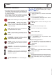
M 2.1 SYMBOLS REV.0 - 11/08 - The symbols used in this manual are designed to call your attention to important aspects of the operation of the machine as well as potential hazards and dangers for persons and things. This symbol is used to draw your attention to the fact that the welder is being used correctly and that the machine or equipment used operates perfectly. STOP - Read absolutely and be duly attentive HIGH VOLTAGE - Attention High Voltage. There can be parts in voltage, dangerous to touch.
M 2.2 SYMBOL REV.0-05/04 ARC WELDING HAZARDS Electric shock from welding electrode or wiring can kill. Wear dry, hole-free insulating gloves and body protection. Do not touch electrode with bare hand. Do not wear wet or damaged gloves. Do not touch live electrical parts. Wet or confined spaces, or if their is una danger of falling. Use AC output ONLY if required for the welding process. If AC output is required, use remote output control if present on unit. Magnetic fields can affect pace-makers.
M 2.2.1 SYMBOL REV.0-05/04 ENGINE HAZARDS Fuel can cause fire or explosion.. Engine fuel plus flames or sparks can cause fire or explosion. Do not weld near engine fuel. Do not spill fuel. If fuel is spilled, clean it up and do not start engine until fumes are gone. Do not smoke while fieling or if near fuel or fumes. Exhaust sparks can cause fire. Use approved engine exhaust spark arrestor in required areas. Keep exhaust and exhaust pipes away from flammables. Do not locate unit near flammables.
M 2.6 INSTALLATION AND ADVICE REV.0 - 11/08 INSTALLATION AND ADVICE BEFORE USE + Use in open space, air swept or vent exhaust gases, which contain the deathly carbone oxyde, far from the work area. Check that the air gets changed completely and the hot air sent out does not come back inside the set so as to cause a dangerous increase of the temperature.
LUFTZIRKULATION UND ABMESSUNGEN INSTALACIÓN Y DIMENSIONES INSTALAÇÃO E DIMENSÕES M 2.7 REV.
M 3 UNPACKING AND TRANSPORT REV.0 - 11/08 ! NOTE + Be sure that the lifting devices are: correctly mounted, adequate for the weight of the machine with it’s packaging, and conforms to local rules and regulations. When receiving the goods make sure that the product has not suffered damage during the transport, that there has not been rough handling or taking away of parts contained inside the packing or in the set. In case you find damages, rough handling or absence of parts (envelopes, manuals, etc.
CTM-MW200 ASSEMBLY M 6.15 REV.0-11/08 Note: Lift the machine and assemble the parts as shown in the drawing ATTENTION The CTM accessory cannot be removed from the machine and used separately (actioned manually or following vehicles) for the transport of loads or anyway for used different from the machine movements.
M 25 Set-up for operation REV.0 - 11/08 LUBRICANT FUEL Please refer to the motor operating manual for the recommended viscosity. ! RECOMMENDED OIL The manufacturer recommends selecting AGIP engine oil. Refer to the label on the motor for the recommended products. ATTENTION Gasoline is highly flammable. Refuel with motor shut off in a flat surfaced well-ventilated area. Do not refuel in the presence of flames. Avoid spilling fuel. Any eventual spilled fuel and fumes are flammable.
M 26 Engine starting REV.0 - 11/08 Lightly pull the start-up knob (73) until meeting resistance, then pull decisively. check daily ATTENTION: ! NOTE Do not alter the primary conditions of regulation and do not touch the sealed parts. Allow the start-up knob to re-enter slowly, avoiding having it knock against the motor and thereby damaging the start-up system. 1. Turn the fuel cock (87) to ON. FUEL COCK STARTER GRIP 2. Switch the choke control (66) to CLOSE N.B.
M 27 Stopping the engine REV.0 - 11/08 Before stopping the engine it is compulsory: - Disconnect or close any power load connected to the system’s auxiliary generation. - Interrupt welding. To shut down the motor: For shut down the motor in case of emergency, turn the motor switch (28) to OFF. In normal conditions, wait for the engine to reach minimum speed automatically 6/7 seconds after the load has been excluded.
Pos. 9 10 12 15 22 23 24 26 27 28 31 73 T X1 BEDIENELEMENTE MANDOS COMANDOS Descrizione Prese di saldatura (+) Prese di saldatura (-) Presa di messa a terra Presa di corrente in c.c. Filtro aria motore Asta livello olio motore Tappo caricamento olio motore Tappo serbatoio Silenziatore di scarico Comando stop Tappo scarico olio motore Comando manuale avviamento Regolatore corrente di saldatura Presa per comando a distanza Description Welding sockets (+) Welding sockets (-) Earth terminal d.c.
M 34 USE AS A WELDER REV.0 - 11/08 ! WARNING Areas for which access by non-authorized personnel is forbidden are: - the control panel (at the front) - the endothermic motor discharge. RECOMMENDED ELECTRODES All the electrodes on the market can be used. CONNECT WELDING CABLES Insert the welding cable plugs completely in the sockets, turning clockwise to lock them in place. PUSH AND TWIST Connect the earth clamp to the negative pole and the electrode holder to the positive.
M 34.1 USE AS A WELDER REV.0 - 11/08 AUTO IDLE Adjusting the maximum engine speed Operation When the engine is switched on it immediately reaches a maximum speed of 3720 rpm for approximately 6/7 seconds for easy start up, after which it automatically decreases and idles at 2650 rpm. It remains at this speed until current is drawn when set to weld or auxiliary power.
VERIFICA E TARATURA DELLA MASSIMA CORRENTE DI SALDATURA CHECKING AND ADJUSTING THE MAXIMUM WELDING CURRENT M 34.2 REV.0-11/08 11 1 12 2 Tu Ti 14 8 2 Sol. 2 dal solenoide from solenoid Sol. 1 2 1 13 7 1 dal ponte chopper from chopper welding bridge dal sensore di corrente from current sensor dal frontale from frontal T T ON OFF Dip switch taratura corrente max. di sald. (*) welding max. current adjustment (*) dall'alternatore from alternator al ponte ausiliario from aux.
PARALLEL ENGINE DRIVEN WELDER MAGIC WELD 200 MAGIC WELD 200 YD - YDE M 34.3 REV.0 - 11/08 How to put two machines in parallel: from the front panels of the machines connect the two positives welding sockets(+) between themselves and the two negative welding sockets bethween themselves. To effect the connection ask for the accessory K2X150. ATTENTION: use fit cables and tight at the connection point.
USE AS A GENERATOR M 37 REV.0 - 11/08 ! WARNING It is absolutely forbidden to connect the unit to the public mains and/or another electrical power source. Areas for which access by non-authorized personnel is forbidden are: - the control panel (at the front) - the endothermic motor discharge. AUXILIARY GENERATION IN AC 230V/50Hz The auxiliary output is drawn by means of a 3 pole socket, the two poles are live, phase and neutral, plus the earth for the machine.
ACCESSORY USE REMOTE CONTROL TC7 M 38.12 REV.0-06/10 PUSH AND SCREW TIGHT The remote control device for regulating the welding current is connected to the front panel by means of a multipole connector. Position welding current adjusting (T) knob at the necessary current value for the diameter and type of electrode. 09/11/99 M38GB When the remote control is connected to the remote control connector (8), it is functional and automatically excludes the front panel regulation.
M 40.2 TROUBLE-SHOOTING REV.
M 40.2.1 TROUBLE-SHOOTING REV.0 - 11/08 Problem Possible cause Solution Incorrect maximum voltage under no-load conditions 1) Incorrect maximum engine speed 1) Adjust the maximum engine speed as shown on page M34. Engine always at idle speed 1) Faulty circuit 1) Replace Engine always at maximum speed 1) faulty circuit 2) Faulty solenoid 1) Replace; 2) Check that the resistance of the solenoid winding is approximately 10 ohm. 1) Dirty petrol filter, dirty air filter, dirty carburetor.
M 43 MAINTENANCE REV.0 - 11/08 ! WARNING ●● Have qualified personnel do maintenance and troubleshooting work. ●● Stop the engine before doing any work inside the machine. If for any reason the machine must be operated while working inside, pay attention moving parts, hot parts (exhaust manifold and muffler, etc.) electrical parts which may be unprotected when the machine is open.
M 45 STORAGE - CUST OFF REV.0 - 11/08 Have qualified personnel prepare the machine for the cust-off. STORAGE In case the machine will not be used for more than 30 days, it should be stored in a suitable area where it is protected from the elements to prevent rusting, corrosion and other damage to the machine. ENGINE Run the engine until it stops from lack of fuel. For long periods of storage, refer to the engine manufacturer’s manual. Clean the machine carefully.
M 55 RECOMMENDED ELECTRODES (In accordance with A.W.S Standard) REV.0-10/03 The information here below are to be intended only as indicative since the above norm is much larger. For further details please see the specific norms and/or the manufacturers of the product to be used in the welding process. RUTILE ELECTRODES: E 6013 Easily removable fluid slag, suitable foe welding in all position. Rutile electrodes weld in d.c. with both polarities (electrode holder at + or -) and in a.c..
M 60 Legenda schema elettrico Electrical system legende Legende des schemas electriques A : Alternatore H : Presa 230V monofase I : Presa 110V monofase R : Unità controllo saldatura T : Regolatore corrente saldatura Y : Ponte diodi saldatura Z : Prese di saldatura W : Reattore c.c.
Stromlaufplan Esquema eléctrico Esquema elétrico (230V version) M 61 REV.
Stromlaufplan Esquema eléctrico Esquema elétrico (110V version) M 61.2 REV.
MOSA div. della BCS S.p.A. Viale Europa, 59 20090 Cusago (Milano) Italy Tel.+39 - 0290352.1 Fax +39 - 0290390466 www.mosa.