
TriStar Manual

22
Installation
Step 6 - Grounding and Ground Fault Interruption
WARNING:
This unit is not provided with a GFDI device. This charge controller must be used with an
external GFDI device as required by the Article 690 of the National Electrical Code for
the installation location.
NOTE:
Conductors identied by the color combination green/yellow shall only be used for earthing
conductors.
AVERTISSEMENT :
L’appareil n’est pas fourni avec un dispositif GFDI. Ce contrôleur de charge doit être
utilisé avec un dispositif GFDI externe tel que requis par l’Article 690 du Code électrique
national de la région de l’installation.
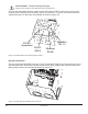
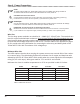
Use a copper wire to connect the grounding terminal in the wiring box to earth ground. The
groundingterminalisidentiedbythegroundsymbolshownbelowthatisstampedintothewiring
box just below the terminal:
Figure 3-4. Ground Symbol
Do not connect the system negative conductor to this terminal. NEC requires the use of an ex-
ternal ground fault protection device (GFPD). The TriStar MPPT 150V does not have internal
ground fault protection. The system electrical negative should be bonded through a GFPD to
earth ground at one (and only one) location. The grounding point may be located in the solar
circuit or the battery circuit.
Per NEC 690.45 (A) and NEC Table 250.122, minimum sizes for copper grounding wire are:
• TS-MPPT-30 10 AWG (5 mm
2
)
• TS-MPPT-45 10 AWG (5 mm
2
)
• TS-MPPT-60 8 AWG (8 mm
2
)
WARNING: Risk of Fire
DO NOT bond system electrical negative to earth ground at the controller. Per NEC
requirements, system negative must be bonded to earth ground through a GFPD at only
one point.
AVERTISSEMENT : Risque d’incendie
NE LIEZ PAS le côté négatif du système à la mise à la terre au niveau du contrôleur.
Selon les exigences du CNE, le côté négatif du système doit être mis à la terre par un
GFPD à un seul point.