
TriStar Manual

18
Installation
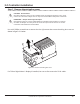
3. Place a mark on the mounting surface at the top of the keyhole.
4. Remove the controller and drill a 3/32” (2.5 mm) hole at the drill mark.
5. Insert a #10 screw (included) into the top pilot hole. Do not tighten the screw completely.
Leave a 1/4” (6 mm) gap between the mounting surface and screw head.
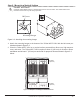
6. Carefully align the keyhole on the TriStar MPPT 150V with the screw head. Slide the
TriStar MPPT 150V down over the keyhole.
7. Check for vertical plumb with a level.
8. Mark two (2) mounting hole locations in the wiring box.
9. Remove the controller and drill 3/32” (2.5 mm) holes at the drill marks.
10. Carefully align the keyhole on the TriStar MPPT 150V with the screw head. Slide the
TriStar MPPT 150V down over the keyhole.
11. The pre-drilled pilot holes should align with the mounting holes in the wiring box. Secure the
controller with two (2) #10 mounting screws.
12. Tighten the keyhole screw.
Step 4 - Adjust Settings Switches
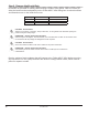
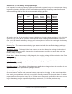
Switch 1: Reserved for Future Use
Settings switch 1 should remain in the “OFF” position.
Mode Switch 1
Solar Charging OFF
future use ON
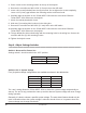
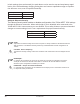
Switches 2 & 3: System Voltage
Four(4)systemvoltagecongurationsareavailableasshowninthetablebelow:
System Voltage Switch 2 Switch 3
Auto OFF OFF
12 OFF ON
24 ON OFF
48 ON ON
The “auto” setting allows the TriStar MPPT 150V to detect the system voltage automatically on
start up. The test is only performed at start up and the detected system voltage will never change
during operation.
Generally,itisbesttochooseaspecicsystemvoltage.Theautodetectfeatureshouldonlybe
used in situations where the system voltage is unknown ahead of time or in systems where the
system voltage may change periodically.