
TriStar Manual


16
Installation
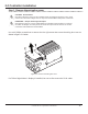
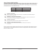
Step 2 - Remove the Knock-Outs
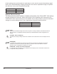
Knockouts are provided for routing cables through conduit or wire glands. Table 3-1 below pro-
vides the knockout sizes and quantity on the TriStar MPPT 150V wiring box. Knockout locations
and dimensions are on the inside front cover.
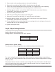
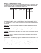
Quantity Trade Size Hole Dimension
8 1/2” or M20 7/8” (22.2 mm)
6 1 “ 1 - 23/64 “ (34.5 mm)
4 1 - 1/4 “ 1 - 23/32 “ (43.7 mm)
Table 3-1. Knockout sizes
CAUTION: Shock Hazard
Always use bushings, connectors, clamp connectors, or wire glands in the knockout openings to
protect wiring from sharp edges.
PRUDENCE : Risque de décharge électrique
Utilisez toujours des bagues, des connecteurs, des raccordements à collets ou des fouloirs dans
les ouvertures an de protéger le câblage des bords coupants.
CAUTION: Shock Hazard
Never route network cables in the same conduit as the power conductors.
PRUDENCE : Risque de décharge électrique
N’acheminez jamais les câbles réseau dans le même conduit que les conducteurs
d’alimentation.
Plan the routing of each conductor that will connect to the TriStar MPPT 150V before removing
any knockouts. The 1/2” (M20) knockouts are ideal for routing network cables, which must be
placed in separate conduit.