
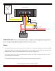
DIAGRAM: Load Control Using a Relay

page 2 of 2ALL.DIG.Load_Control_Using_A_Relay.01.EN
© 2013 Morningstar Corporation. All rights reserved.
page 2 of 2
IMPORTANT: This is not intended to be a complete system diagram; fusing, discon-
nects, and grounding should comply with local electric codes.
Notes:
Used when the load is an inverter, pump, motor, compressor, or exceeds the controller’s Load current rating.•
The Flyback Diode is recommended to clamp inductive voltage spikes when the Relay is de-energized. The •
Diode should be rated to at least the maximum current drawn by the Relay coil.
•
The Charge Control above can be any Morningstar controller with built-in Load terminals and LVD (low •
voltage disconnect) functionality.
For detailed installation information, please consult the respective product manual.•
12 Volt
+
-
+ -
PV Array
-> LOAD
N/O Relay
Flyback Diode
Charge Controller
Array +
Array -
Battery +
Battery -
Load +
Load -