
Installation Manual


6
• Tighten each terminal clamping screw to 20 inch-pounds of
torque.
• The SunLight is designed to regulate power from a PV array.
Other generators can be connected directly to the battery,
however, with no effect on the SunLight.
• Do not connect any system wires (Solar, Battery, Light) to the
SEALED OR FLOODED SELECT
terminal.
Refer to the connection diagram on page 3 to illustrate each of the
following installation steps.
1. Inspect the controller for shipping damage. If possible, mount
the SunLight to a vertical surface.
Allow a minimum of 5 cm (2 inches) space above and below the
controller for air flow. Protect the controller from direct sunlight
or other heat sources.
The SunLight can be mounted outdoors. Avoid mounting in
direct rain such that water could collect under the cover. If
installed in an enclosure, some ventilation is recommended to
minimize operating temperatures.
N
OTE
:
The SunLight is very corrosion resistant. The case is
hard coat anodized, cover screws are stainless steel,
the circuit is encapsulated, and the terminals are
copper and nickel plated brass.
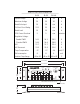
2. Confirm that the Solar array and loads will not exceed the
current ratings of the Sunlight controller being installed.
N
OTE
:
A SunSaver can be connected in parallel with a
SunLight for additional amps of solar charging. Make
sure each controller’s input rating is not exceeded.
The lighting load can only be connected to the
SunLight and cannot exceed the load rating.
3.
CONNECTION ORDER
The label has each system connection
numbered from 1 to 6. This is the recommended order of system
connections. The
BATTERY
must be connected before the
SOLAR
to properly start the microcontroller.
4.
BATTERY
Connect the 12-volt (or 24V) system battery. The
green LED will not light. If the red LED (LOAD DISCONNECT)
lights and stays lit, the battery charge state is low and should be
recharged before completing the installation.