
Operation Manual


14
INSTALLER
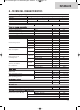
9.- FUNCTION DIAGRAM
1.-Gas inlet
2.-Water inlet
3.-Gas filter
4.-Lower body
5.-Upper body
6.-Water regulator
7.-Pressure test point
8.-Water filter
9.-Power selector
10.- Servovalve
11.- Injector
12.- Distributor
13.- Main body
14.- Electrode unit
15.- Supply and fan control circuit
16.- Burner
17.- Heat exchanger
18.- Fan unit
19.- Air pressure switch
20.- Ignition box and ionisation safety
device
21.- Micro switch
22.- Distributor connector
23.- Venturi
24.- Sealed chamber
25.- Ø 60-100 coaxial output
26.- Supply cable
27.- Water flow switch
28.- NTC
1-10.010.649-ingles:1-10.005.856-ingles 24/03/14 17:42 Página 14