
Specifications


19
Communication lines
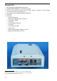
Every DataLab PC is equipped with standard RS-232C serial line, USB ports and Ethernet
interface. DataLab PC 800 and DataLab PC 600 contain 2 USB ports, DataLab PC 1200,
DataLab PC 1000 and DataLab PC 610 offers 4 USB ports on ATX panel.
DataLab PC 1200, DataLab PC 800, DataLab PC 610 and DataLab PC 600 can be also equipped
with isolated RS-485 serial interface. RS-485 module is optional and must be ordered sep-
arately. The RS-485 is connected to internal serial interface so the RS-232C interface on
the ATX panel remain free for other usage.
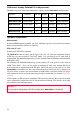
RS-485
The RS-485 serial line uses three-pole connector. Communication line is isolated. Two-
colors LED 1 indicates communication: green light—transmission, red light—receiving.
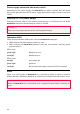
A B GND
RS-485
+
12 V DC L1 L2
Figure 5 Auxiliary 12 V DC
output and RS-485 connectors
RS-485 settings
The printed circuit board is accessible after removing the computer cover. RS-485 inter-
face module is plugged (piggybacked) to PWR board, which contains connectors.
Jumper settings
• J1—controls direction control. Direction can be controlled according to RTS signal or
automatically depending on the transmitter activity. Automatic direction control re-
quires setting of time delays according to the communication speed by the RT resistor.
Automatic direction control (default)
RTS-controlled direction
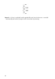
• RT—defines time delay of automatic direction control. The 68 kΩ resistor is used by
default. The RT value can be calculated from the equation
τ [ms] = 7 × RT [MΩ], where
τ is a time constant. For instance for the speed 19,200 Bd with 1 start bit, 8 data bits,
1 stop bit and 1 parity bit time constant is: 11 bits / 19,200 bps = 0.573 ms; which
corresponds to RT = 81 kΩ.
• RA, RB, RC—terminating resistors. 360 Ω resistors are used by default.