
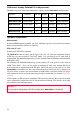
Specifications


17
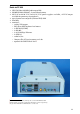
Connector placement
There is a standard ATX connector panel on one side of the DataLab PC. The power supply
connectors and main switch, as well as CF slot, 12 V DC auxiliary output and possible RS-
485 interface connector are placed on the opposite side.
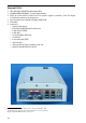
ATX panel
Connector placement on ATX panel depends on individual configuration. Panel picture
is shown in individual configuration descriptions. Thorough description can be found in
respective motherboard documentation, supplied with every computer.
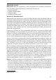
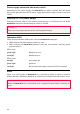
Power supply and auxiliary circuits
I
O
RS-485
L1
L2
230 V AC
Main switch
Auxiliary power supply
+12 V
DC
Compact Flash Card
Figure 3 Power supply connectors
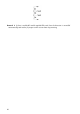
USB watchdog, auxiliary power supply, indication LEDs and RS-485 interface are placed
on the separate PWD printed circuit board. This board is accessible after removing the
computer cover.
Figure 4 PWR printed circuit board