
Specifications


14
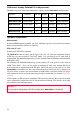
Differences among DataLab PC configurations
The following table summarizes differences among various DataLab PC configurations.
interface
Ethernet USB 2.0 RS-485 CPU memory SDRAM
DataLab PC 1200 1×1 Gbps 4× optional 1,2 GHz DDR2, 533 MHz
DataLab PC 1000 1×10/100 Mbps
4× no 1 GHz DDR2, 533 MHz
DataLab PC 800 1×10/100 Mbps 2× optional 800 MHz DDR, 400 MHz
DataLab PC 610 2×10/100 Mbps 4× optional 600 MHz DDR, 266 MHz
DataLab PC 600
1×10/100 Mbps 2× optional 600 MHz
DDR, 266 MHz
Optional components
RAM memory
Standard DIMM memory modules are used. Memory capacity can be chosen according
to the current memory modules availability.
HDD and CF card
Standard 2.5" IDE HDD is optional.
The DataLab PC contains one slot for Type 1 CF card. CF card are connected directly
to IDE bus so it must work in “True IDE” mode. It is possible to use CF card with or
without HDD. The embedded operating system can boot from CF (Windows XP Embedded
or Windows CE).
The Windows XP Embedded operating system protects CF card against writes with so-
called “write filter”. So it can be useful to combine CF card with another IDE Flash
disk connected to another (internal) IDE port. IDE Flash disk can be used e.g. to store
Control Web archive files etc. Data are written directly to IDE Flash disk as opposite to
CF card, where all writes are accumulated in RAM buffers and these buffers are physi-
cally committed to CF card upon executing of explicit command (see chapter Operating
system).
CF card works as IDE master on secondary IDE channel by default. Master or slave mode
can be selected by jumper J1 on the CF slot printed circuit board. This board is accessible
after removing the computer cover.
Warning 1
It is possible to manipulate with CF card only when DataLab PC is turned off!