
Instruction manual


!
!
250 ft 3 4 5 8 13 W
300 ft
4 5 6 10 16
W
400 ft
5 6 8 13 21
W
500 ft
6 8 10 16 26 W
600 ft 8 10 12 19 31 W
800 ft
10 13 16 25 42
W
1000 ft 13 16 20 32 52 W
1250 ft 16 20 25 40 65 W
1500 ft 19 24 30 48 78 W
1750 ft 23 28 35 55 91 W
2000 ft 26 32 40 63 104 W
2500 ft
32 40 49 79 131 W
3000 ft 39 48 59 95 157 W
3500 ft
45 56 69 111 183
W
4000 ft 52 64 79 127 209 W
5000 ft 65 80 99 158 261 W
6000 ft
78 95 119 190 313 W
8000 ft 104 127 158 253 418 W
W
W
W
W
W
W
W
W
W
W
W
W
W
W
W
W
W
W
W
W
W
W
W
W
W
W
W
W
W
W
W
W
W
W
W
W
W
W
W
W
W
W
W
W
W
W
W
W
W
W
W
W
W
W
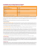
Unshielded Twisted-Pair Wire Gauge (AWG)
Cable
Distance
W
W
W
W
W
W
W
W
W
W
W
W
W
W
W
W
W
W
2422201918
Unshielded Twisted-Pair Wire Gauge (AWG)
Distance
2422201918
Unshielded Twisted-Pair Wire Gauge (mm)
Distance
0.50.60.70.81.0
3 4 5 8 13 W
4 5 6 10 17 W
5 7 8 13 21
W
6 8 10 16 26 W
9 10 13 21 34 W
13 16 19 31 51 W
17 21 26 42 69 W
21 26 32 52 86 W
26 31 39 62 103 W
32 39 49 78 129 W
38 47 58 94 154 W
43 52 65 104 171 W
51 63 78 125 206 W
64 78 97 156 257
W
77 94 117 187 309 W
102 125 156 249 411 W
W
W
W
W
W
W
W
W
W
W
W
W
W
W
W
W
W
W
W
W
W
W
W
W
W
W
W
W
W
W
W
W
W
W
W
W
W
W
W
W
W
W
W
W
W
W
W
W
Cable
Cable
W
W
W
W
W
W
W
W
W
W
W
W
W
W
W
W
75 m
100 m
125 m
150 m
200 m
300 m
400 m
500 m
600 m
750 m
900 m
1000 m
1200 m
1500 m
1800 m
2400 m
75 m
100 m
125 m
150 m
200 m
300 m
400 m
500 m
600 m
750 m
900 m
1000 m
1200 m
1500 m
1800 m
2400 m
3 5 6 9 13
W
4 7 9 12 18 W
6 8 11 15 22 W
7 10 13 18 27 W
9 13 17 24 36 W
13 20 26 36 54 W
18 27 35 48 72 W
22 33 43 60 90 W
26 40 52 72 108 W
33 50 65 89 135 W
40 60 78 107 162 W
44 66 86 119 179 W
53 80 104 143 215 W
66 100 130 179 269 W
79 120 155 215 323 W
106 159 207 286 431 W
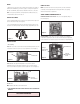
2. Connect the other end of the unshielded twisted pair cable to the NVT receiver.
CAUTION: The unshielded twisted pair video signal is polarity dependent. The
positive video wire for each camera MUST be connected to the
positive terminal on the NVT receiver, and negative MUST be
connected to negative.
3. When using unshielded twisted pair cable you DO NOT need the BNC connector. All
four BNC connectors are provided inside the housing for testing purposes. Be sure that
there is no video connection other than the unshielded twisted pair cable.
Wiring Notes
Wire — What toDO
1. DOuse point-to-point Unshielded Twisted Pair wire, gauge 24 or thicker, stranded
or solid, Category 2, 3, 4, or 5.
2. The video signal may co-exist in the same wire bundle as other video, telephone,
data, control signals, or low-voltage power. It is also OK to run NVT video signals in or
near electromagnetic elds (in accordance with National Electrical Code, local, or other
local safety requirements).
3.DOmeasure the wire distance. Use only transceivers that are designed for that
distance.
4.DOmake sure the pair of wires carrying the video signal is sent as a twisted pair
(e.g. the blue-white/white-blue wires twisted together as a pair), not a “split-pair” (e.g.
blue-white conductor, part of one pair/orange-white conductor, part of another pair).
Wire — WhatNOTtoDO
1.DO NOT USE SHIELDED TWISTED PAIR WIRE.It will severely degrade the dis-
tance performance. Short runs may be used with some signal degradation (for example
elevator traveler cables). Multi-pair wire with an overall shield is OK.
2.DO NOT USE UN-TWISTED WIRE. It will reduce the NVT product’s inherent
interference immunity.
3.DO NOTallow your installation to have “bridge-taps”, loading coils, talk-battery, or
MOV type protectors. Bridge-taps are where a twisted pair is connected to two twisted
pairs (such as an extension phone at home). Bridge-taps cause reections as the
signal propagates, resulting in “ghosts” in the video image, and are to be avoided.
4. If the phone company is providing the cable runs between buildings, make sure it’s
“dry copper” i.e. it should have none of the following: dial-tone, 48 volts, loading coils,
bridge-taps, switching, or long paths to the phone company’s central ofce and back.
5. Due to near-end crosstalk, DO NOTsend a transmit and a receive signal in the
same wire bundle. Exceptions: Less than 1,000 ft (300m), or Category 5 cable, up to
2,000 ft (600m) are OK.
6. DO NOTsend “Up-the-Coax” Pan/Tilt/Zoom signals through active (amplied) NVT
transceivers.
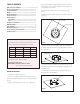
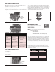
Measure your wire distance
Note:All NVT quoted distance specications include any coax in the
run. It is recommended that the wire distance be measured to ensure
that the capability of the NVT product is correct.
Wire resistance may be measured with an ohm-meter by shorting
the two conductors together at the far end, and measuring the
loop-resistance out and back. Compare your readings with the charts
below.
7. For safety, never put NVT signals in the same conduit as high-voltage
wiring.
8.WARNINGto reduce a risk of re or electrical shock, do not expose
this product to rain or moisture.