
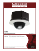
Instruction manual


NOTE: This hi-res color camera uses a 1/4" chip and a 3-6mm auto iris lens. It is
comparable to a 1/3" chip using a 4-9mm auto iris lens.
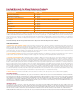
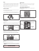
The operational settings are dened by four dip switches located on the side of the PC
Board (Figure 12 and 13). Moving the switches to the UP position will activate specic
settings. Refer to the chart below.
Figure 12
Figure 13
Dip Switch UP DOWN
SERIAL NUMBERS BEGINNING WITH CB
SERIAL NUMBERS BEGINNING WITH CT
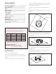
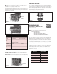
FIXED AND FIXED VARI-FOCAL LENSES. There are no user adjustable settings on
these units (Figure 14)
AUTO IRIS LENSES: The auto iris can be adjusted if needed. See the Troubleshooting
section for instructions.
NVT INSTRUCTIONS
The cameras included in the Q-View™ series have the option of transmitting video
signals to NVT receivers via unshielded twisted pair cable. You must purchase the
receiver separately. Instructions for connecting the receiver end of the unshielded
twisted pair cable will be included with the NVT receiver. Following are instructions
for connecting the unshielded twisted pair cables to the RJ45 (Cat. 5) cable running
outside your housing.
UNSHIELDED TWISTED PAIR
VIDEO WIRING
1. Video for all four cameras is contained in the one RJ45 (Cat. 5) cable. An RJ45
female coupling is provided so that all connections can be made with an RJ45
connector. The following is the wiring diagram for the four twisted pair wires that are
included with the Cat. 5 cable.
NOTE:The customer must purchase the Video Transceiver from
PIN WIRE COLOR CAMERA NUMBER
COMPLETION OF INSTALLATION
Once all connections and adjustments have been made reattach the trim ring/dome
assembly by pressing in and sliding the three at springs into the housing (Figure 15).
Make sure the springs are aligned with the three spring slots. You will feel all three
springs snap into place when the dome is correctly secured into place. Rotate the
dome for nal proper positioning of the liner and camera.
Figure 15