© 2011, Moog Videolarm, Inc. All Rights Reserved QMR QView™ Series Ceiling Mount Dome www.videolarm.com Installation and Operation Instructions for the following models: QMRT2-70NA Recessed tinted indoor/outdoor ceiling dome, with two (2) Day/Night cameras, 3-9mm auto-iris lens QMRT4-70NA Recessed tinted indoor/outdoor ceiling dome, with four (4) Day/Night cameras, 3-9mm auto-iris lens Before attempting to connect or operate this product, please read these instructions completely.
IMPORTANT SAFEGUARDS 1 Read these instructions. 2 Keep these instructions. 3 Heed all warnings 4 Follow all instructions. 5 Do not use this apparatus near water. 6 Clean only with damp cloth. 7 CAUTION RISK OF ELECTRIC SHOCK DO NOT OPEN Do not block any of the ventilation openings. Install in accordance with the manufacturers instructions. 8 9 SAFETY PRECAUTIONS Cable Runs- All cable runs must be within permissible distance.
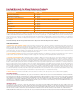
Limited Warranty for Moog Videolarm Products Moog Videolarm warrants these products to be free from defects in material or workmanship as follows: PRODUCT CATEGORY PARTS \ LABOR All Enclosures and Electronics* Five Poles/PolEvators™/CamEvator Three (3) Years Warrior Series™/Q-View™/IR Illuminators Five (5) Years SView Series™ Five (5) Years **6 months if used in auto scan/tour operation Controllers Five (5) Years Power Supplies Five (5) Years EcoKit Three (3) Years Accessory Brackets F
TABLE OF CONTENTS 4. Remove the trim ring/dome assembly by pulling on the outside of the trim ring. Cable and Power Guidelines.............................................1, 11 Electrical Specifications................................................... 1 Housing Installation..........................................................1 Wiring............................................................................... 2 Camera Adjustment..........................................................
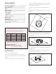
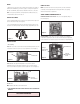
WIRING CAMERA SETTINGS 1. Make the proper connections to the incoming power. The RED wire is POSITIVE (+), the BLACK wire is NEGATIVE (-) (For reference purposes. Polarity is not important in this unit). The GREEN wire, labeled Ground, is GROUND for VAC or VDC connections. NOTE: To determine which camera is used in your unit, locate the serial number on the inside of the housing. Match the two letter prefix with the corresponding instructions included here for adjustments.
MC CAMERA DIP SWITCH SETTINGS CHART SERIAL NUMBERS BEGINNING WITH MC The operational settings for the camera are defined by ten dip switches located on the PC Board (Figure 9). Moving the switches to the on position will activate each setting. Factory defaults are pictured below (Figure 10 and 11).
COMPLETION OF INSTALLATION SERIAL NUMBERS BEGINNING WITH CB NOTE: This hi-res color camera uses a 1/4" chip and a 3-6mm auto iris lens. It is comparable to a 1/3" chip using a 4-9mm auto iris lens. The operational settings are defined by four dip switches located on the side of the PC Board (Figure 12 and 13). Moving the switches to the UP position will activate specific settings. Refer to the chart below.
2. Connect the other end of the unshielded twisted pair cable to the NVT receiver. CAUTION: The unshielded twisted pair video signal is polarity dependent. The positive video wire for each camera MUST be connected to the positive terminal on the NVT receiver, and negative MUST be connected to negative. 3. When using unshielded twisted pair cable you DO NOT need the BNC connector.
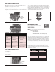
MR7 Exploded Diagram and Replacement Parts List 1 2 3 4 5
Part Number 1 Description RPOD01 PC Board and Input cables video/power RPOD01-NVT PC Board and Input cables video/power with NVT 2 RPQF02 multi CAMERA metal base BRACKET 3 RPQF03 camera bracket and hardware RPQF03-20NA camera bracket and hardware - (20 na models) 1A 4 RPQF04 plastic articulated bracket 5 RPQF20NF3 hi-res b&w 3.6 fixed lens RPQF20NA hi-res b&w 4-9mm auto iris varifocal RPQF50NF3 hi-res color 3.
TROUBLESHOOTING If you experience problems with the camera picture please check these simple troubleshooting procedures for possible solutions before calling technical support. STATIONARY OR SCROLLING HORIZONTAL LINES ON SCREEN GROUND LOOPS Generally a horizontal line on screen, whether moving or stationary, means you have a ground loop problem. The video shield should only be connected to ground through the monitor or other electronic equipment that uses the video signal.
NVT TROUBLESHOOTING If you are experiencing problems, attempt to simplify your setup. Test each cable segment separately. For example, test the camera and monitor together without the other equipment. Then add in the NVT transceivers, back-to-back. Test each segment of a long cable-run independently. Attempt to isolate the problem. Below are problems that may be encountered. If the suggestions below are not helpful, or the recommendations are not effective, please call NVT’s customer support.
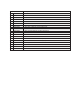
CABLE AND POWER GUIDELINES This chart shows the proper current needed for power supplies for Q-View Series cameras. Use Class 2 Power only. Input voltage must be 24 VAC/VDC. CAMERAS CURRENT POWER 1 VOLTAGE 24 VAC/VDC 102mA 2.5W 2 24 VAC/VDC 210mA 5W 3 24 VAC/VDC 331mA 7.9W 4 24 VAC/VDC 487mA 10.
Product Registration/Warranty Thank you for choosing Moog Videolarm. We value your patronage and are solely committed to providing you with the highest quality products available and superior customer service. Should a problem arise, rest assure that Moog Videolarm stands behind its products by offering impressive warranty plans: 3 Years on all Housings, Poles, Power Supplies, and Accessories and 5 Years on camera systems (SView, QView, Warriors), and InfraRed Illuminators.