
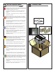
Operating instructions
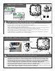


Active Solid-State
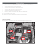
The third and least common method is the emitter follower where the camera output supplies the current used for detection. In this conguration is shown in Figure 7.
Striped Wire +
I/O Detect Cable
Camera
Solid State
Sourcing Relay
+ Volts
Plain Wire -
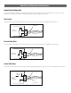
Figure 7: Active Solid-State Relay I/O Detect Connection
Output Relay Conguration and Connections
Output Relay Conguration
The relay output congurations vary based on the manufactures design. Because of these variations, the IP Reset I/O Detect input needs to operate in one of three
ways. Refer to your camera user manual for more information regarding the output relay conguration of your camera.
Striped Wire
I/O Detect Cable
Camera
Dry Contact
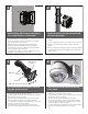
Passive Solid-State
The second method is similar, requiring the IP Reset to supply current to an open collector output transistor. This conguration is shown in Figure 6.
Striped Wire
I/O Detect Cable
Camera Open
Collector Relay
Figure 6. Passive Solid-State Relay I/O Detect Connection
Figure 5: Dry Contact Relay I/O Detect Connection
Dry Contact
The rst and most common method requires the IP Reset to supply current to the dry contacts of a relay. This conguration is shown in Figure 5.