
Operating instructions


Hardware Installation
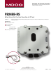
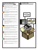
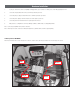
IP Reset power box PB24BBRS
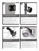
Attach the brown and black wire to the blue and purple wire of the dome. Inside the dome, attach the purple and blue wire to the alarm output of the camera.
Brown
Black
Blue
Purple
IP
R
S
0
1
S
e
r
ia
l #
0
0
1
6
5
6
Tested
to comp
ly
with FCC s
tanda
rds
V
in
Vo
u
t
A
la
rm
2
4
Va
c
R
e
d
R
e
d
/B
la
c
k
B
row
n
Ora
n
g
e
O ra
n
g
e
/B
la
c
k
B
la
c
k
1
2
V
d
c
R
e
d
(+) R
e
d
/B
la
c
k
(+)
Ora
n
g
e
(-) O ra
n
g
e
/B
la
c
k
(-)
1. Locate your camera in the Camera Compatibility Chart (Appendix A). If your camera is not listed, please contact Moog at (800)-554-1124.
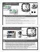
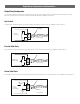
2. Connect the striped I/O Detect wire to the I/O terminal specied for your device.
3. Connect the plain (no stripe) I/O Detect wire to the I/O terminal specied for your device.
4. Connect the power output pin from the IP Reset to the Power input on your device.
5. Connect the power from the transformer to the power input in the IP Reset.
6. Add your device’s conguration to the IP Reset Manager Software or Network video recording (NVR) software.
Note 1: Connection polarity MUST be observed for all devices.
Note 2: If the input connections need to be modied, the striped wire is plus VDC and the solid wire is ground (0 VDC).