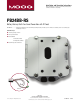
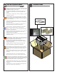
Installation and Operation Instructions Before attempting to connect or operate this product, please read these instructions completely. PB24BB-RS Battery Backup Multi-Functional Power Box with IP Reset PB24BB-RS............... Rugged cast aluminum power box PB24 plus battery backup. Provides up to 25 minutes of extended power. Pole mounting clips included plus IP Reset Installation Steps ➊ Check the package contents ➋ Select Operation Mode ➌ Install Hardware a. Timed Reset Mode b.
IMPORTANT SAFEGUARDS 1 Read these instructions. 2 Keep these instructions. 3 Heed all warnings 4 Follow all instructions. 5 Do not use this apparatus near water. 6 Clean only with damp cloth. 7 CAUTION RISK OF ELECTRIC SHOCK DO NOT OPEN Do not block any of the ventilation openings. Install in accordance with the manufacturers instructions. 8 9 SAFETY PRECAUTIONS Cable Runs- All cable runs must be within permissible distance.
Product Warranty Registration Register Your Products Online www.moogS3.com/technical-support/product-registration Moog values your patronage. We are solely committed to providing you with the highest quality products and superior customer service. With 3-Year and 5-Year warranties (depending on the product purchased) we stand behind every product we sell. See full warranty details at www.moogS3.
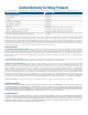
Limited Warranty for Moog Products Moog - Decatur Operations, subsequently referred to as “Manufacturer,” warrants these products to be free from defects in material or workmanship as follows: PRODUCT CATEGORY PARTS \ LABOR All Enclosures and Electronics Five (5) Years Accessory Brackets Five (5) Years Controllers Three (3) Years Power Supplies / IR Illuminators Three (3) Years Poles / PolEvators / CamEvator Three (3) Years Warrior Series™ / Q-View™ Three (3) Years ™ Three (3) Years 6 months
Electrical Specifications PB24BB English Input Power: 120 VAC/240VAC 1A/.5A Power Consumption: 1Amp (120 Watts) at 120 VAC Power Output: 84 VA at 24 VAC 52 Watts Heater/Blower 32 Watts Camera Power An all pole main switch with a contact of at least 3mm in each pole shall be incorporated in the electrical installation of the building. Tools Required: .150” Flathead Screwdriver 7/16 Wrench or Socket 9/16 Wrench or Socket Español Energía De Entrada: 120 Consumo De Energía de VAC/240VAC 1A/.
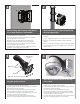
1 2 Wall Mounting: Attach unit securely with (4) 3/8” or 8mm hardware (not supplied). • La pared que monta la caja de la energía es posible, pero el hardware no es incluido. • Le mur montant la boîte de puissance est possible, mais le matériel n'est pas inclus. • Die Wand, die den Energie Kasten anbringt, ist möglich, aber die Kleinteile sind nicht enthalten. • A parede que monta a caixa do poder é possível, mas a ferragem não é incluída.
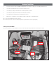
4b INPUT: (120VAC or 240VAC) 5b 220-240VAC INPUT 110-120VAC INPUT 240Vac 120Vac Input Input Main Switch Line (L) and Neutral (N) wires should be connected as marked on the board and plugged into the corresponding voltage for the input single phase. Los alambres de la línea (l) y del hilo neutro (n) se deben conectar según lo marcados en el tablero y tapados en el voltaje correspondiente para la monofásico de la entrada.
Operating Modes The IP Reset operates in one of two modes, Intelligent Reset Mode and Timed Reset Mode. IP Reset automatically detects the operating mode by monitoring the I/O Detect input. If IP Reset detects a change in the I/O Detect input, it will enter the Intelligent Reset mode. Otherwise, IP Reset will remain in Timed Reset mode. You can choose to use Timed Mode by twisting the I/O Detect wires together and securing them with the wire nut.
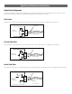
Output Relay Configuration and Connections Output Relay Configuration The relay output configurations vary based on the manufactures design. Because of these variations, the IP Reset I/O Detect input needs to operate in one of three ways. Refer to your camera user manual for more information regarding the output relay configuration of your camera. Dry Contact The first and most common method requires the IP Reset to supply current to the dry contacts of a relay. This configuration is shown in Figure 5.
Hardware Installation 1. Locate your camera in the Camera Compatibility Chart (Appendix A). If your camera is not listed, please contact Moog at (800)-554-1124. 2. Connect the striped I/O Detect wire to the I/O terminal specified for your device. 3. Connect the plain (no stripe) I/O Detect wire to the I/O terminal specified for your device. 4. Connect the power output pin from the IP Reset to the Power input on your device. 5.
Hardware Installation (cont.
Software Installation (For a windows based PC) If there is a preexisting version of the IP Reset Manager Software on your computer go to “Add/Remove Programs “from the MS Windows Control Panel and remove it before beginning a new software installation. To remove a preexisting IP Reset Manager Installation, go to the Windows “Control Panel” and click on the “Add or Remove Programs” software icon.
Software Installation (For a windows based PC continued) In response to the confirmation box “Add or Remove Programs” message. Click “Yes”. A window may show up as follows: Let this window run to completion. Following the above window if you are removing the application from a computer with the Windows Vista operating system, a window (not shown) may appear with the title “User Account Control”.
IP Reset Manager Software Installation Guide After you have fully removed any preexisting installations of IP Reset Manager (see section “Removing IP Reset Software” from your system), run program and download from the Web Site.
IP Reset Manager Software Installation Guide Continued A Window pops up that says “Select Installation Folder”, if the radio button “just me” is selected, (shown below) than change it to the radio button “Everyone”, as shown below A window will appear that says, “Confirm Installation”, Click “Next >” to confirm the installation!
IP Reset Manager Software Installation Guide Continued Following the above window if you are installing the IP Reset application from a computer with the Windows Vista operating system, a window (not shown) may appear with the title “User Account Control”. It will say “An Unidentified Program Wants to Access Your Computer”, if this window appears you should click the “Allow” option.
Older machines may require downloading Microsoft Dot Net If you are on an older windows machine that does not have a current version of Microsoft’s Dot Net libraries, you may get a message from Windows requiring you to download the latest version of Microsoft .Net. At this point you will have log on to Microsoft at: http://msdn.microsoft.com/en-us/netframework/default.aspx And download the latest version of Microsoft’s .Net libraries. After doing this double click on the downloaded files to install .Net.
You are now ready to run the IP Reset Configuration Software. For usage information refer to application users document “IP ResetSoftwareUsersGuide.pdf”: “C:\Program Files\Moog\IP Reset\IP Reset_Software_User_s Guide.pdf” is the application manual used to configure IP Reset devices from the computer. It describes installing the IP Reset devices to work with your cameras or other devices.
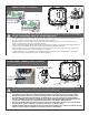
7 The battery backup system is designed to be used only with 12VDC Cameras. 8 When used with the FDW75C2N or RHW75C2N remove Dome from housing. • El sistema de reserva de batería se diseña para ser utilizado solamente con las cámaras fotográficas 12VDC. • Cuando está utilizado con el FDW75C2N o el RHW75C2N quite la bóveda de la cubierta. • Le réseau de réserve de batterie est conçu pour être employé seulement avec les appareils-photo 12VDC.
6 7 5 4 3 2 1 7 N/S IPRS01 IP Reset Replacement Battery Battery Bracket RPVL3085 RP70BAT1214 Battery Charger Curcuit RP70TVLSMP3 RP70TRAN11