
User Guide
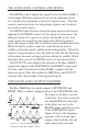
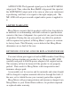

The pedal cable should be shielded, with the shield connected to
the sleeve terminal. See Figure 14.
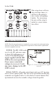
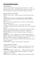
When connecting one or more pedal control input jacks to a
source of external control voltage such as an analog synth or a
MIDI-to-CV converter, you should use patch cords with tip-ring-
sleeve phone plugs. The ring terminal on the plug should not be
connected to anything, so that the MF-105B’s source of +5 volts
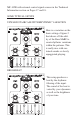
Figure 14 – Correct wiring for an expression
pedal
An expression pedal for
use with the MF-105B
should contain a 50KW
or 100KW potentiometer
which is connected from the
sleeve to the ring terminals.
The potentiometer wiper is
connected to the tip terminal.
Figure 15 – Correct wiring for a TRS CV
patch
is not shorted out. Or, if you do
not plan to use any expression
pedals with your MF-105B
but would like to apply control
voltages to one or more pedal
control inputs, you can use
patch cords with regular two-
conductor phone plugs. These
will short out the +5 volt supply to the ring contacts. This voltage
is current-limited, so you won’t burn anything out, - but no pedal
will work in any of the pedal control jacks if a tip-sleeve plug is
plugged into even one of the pedal jacks.
Applying a varying voltage to the tip terminal of a pedal control
input jack has the same effect as turning the corresponding knob. A
voltage change of about 5 volts at the tip terminal is equivalent to
turning the corresponding knob through its entire range. You can
‘program’ your MF-105B performance parameters entirely from
external control voltages, by turning the ENVELOPE, MIX, and
RATE control knobs to 5, and feeding 0 to +5 Volt programming
voltages to the tips of the pedal control input jacks. The LFO/
SWEEP jack can also receive 0 to +5 Volt programming voltages.