WELCOME TO THE WORLD OF MOOGERFOOGER® ANALOG EFFECTS MODULES! Your MF-108M Cluster Flux is a rugged, professional-quality instrument, designed to be at home on stage or in the studio. Its great sound and jawdropping effects come from state-of-the-art analog circuitry, designed and handcrafted by our team at MOOG Music in Asheville, North Carolina. The MF-108M is rooted in the analog wizardry of Bob Moog’s moogerfooger designs.
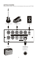
GETTING STARTED Here are some simple instructions on how to plug in and try your new MF-108M.
1. Unpack your Cluster Flux and gently tap the wooden side pieces of your new moogerfooger to wake it up after the long journey to its new home. 2. Connect the instrument cable from your sound source to the AUDIO IN jack. You can feed virtually any instrument or line-level signal through your MF-108M. 3. If you plan on using MIDI, connect a MIDI Cable from the out on the MIDI controller of your choice to the MF-108M’s MIDI in. NOTE: The Cluster Flux defaults to MIDI Channel one.
1. CLASSIC FLANGING This effect features an up-and-down modulation of the input signal. Some describe it as a whooshing or jet plane sound. •Move TIME left to raise flanging frequency and right to lower it •Try negative FEEDBACK for a lower pitched, hollow flange •For best flanging results MIX control should be mostly wet •As RATE increases, try decreasing the AMOUNT for more musical results 2. CLASSIC CHORUS This effect features a subtle up-and-down modulation of the input signal’s pitch.
3. VIBRATO This effect features a slight up-and-down modulation of the input signal’s pitch monitoring only the wet signal. •Adding FEEDBACK to vibrato gives it a metallic edge •The sine wave offers the most natural finger vibrato sound •Increasing the RATE modifies the speed of up and down vibrato. This will also increase the audible pitch modulation •As RATE increases, try decreasing the AMOUNT for more musical results 4.
5. PEDAL FLANGE This setup requires an Expression Pedal such as the Moog EP-2. Pedal Flanging allows real-time control of the flange frequency and can be played like a wah-wah effect.
7. RAMP WAVE PITCH MOD The LFO Ramp wave can be used for creative rhythmic pitch cluster effects. This unusual effect features a rising modulation of the pitch followed by a sudden drop. •Tune the TIME control in conjunction with the AMOUNT and RATE controls for the desired range of pitch modulation.
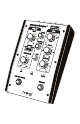
THE CLUSTER FLUX FRONT PANEL DRIVE Control - Sets the input sensitivity of the Cluster Flux. This control is only active when the Effect is on. The available gain is from -7dB to +28dB nominal. The Cluster Flux is designed to work with instrument or line-level signals. LEVEL LED - Works in conjunction with the DRIVE control. Red indicates clipping. Yellow indicates the nominal signal level for best signal-to-noise ratio. Green indicates the presence of signal below the nominal level.
Any position between the two will blend Wet and Dry signal to the outputs. DELAY TIME - Sets the length of Delay from the BBD delay line based on the Range switch setting. In Flange Mode, with AMOUNT set to 0, the Delay Time changes from .6 msec to 10 msec nominal. In Chorus mode this change is 5 msec to 50 msec nominal. RANGE - Sets the range of delay times available to the DELAY TIME control. Flange selects a range of shorter delay times while Chorus selects a range of slightly longer delay times.
LFO AMOUNT - Sets the overall amount of modulation of the delay time by the LFO. Note: As the LFO Amount increases, the functional range of the Delay Time control is decreased, so that the maximum and minimum delay times are not exceeded. BYPASS - Used to turn the Effect On and Off. When the effect is On, the Bypass LED is Green. When the effect is Off, the Bypass LED is Red. TAP TEMPO - Dedicated switch used for setting the LFO Rate to a musical tempo.
output in Stereo applications. The default configuration is that the Right Output carries a mix of the Dry signal plus the inverted Wet signal. When the outputs are panned hard left and right, this creates a rich stereo effect. In this mode, when both outputs are mixed together and panned to the center the wet signal is cancelled. Refer to the section entitled “Output Configuration” for information on other stereo output modes.
Refer to the MIDI section of this manual for use of the Cluster Flux with other MIDI devices. POWER - For connecting to the supplied power adapter Note: Use only the proper power supply to avoid damage to the device. Make sure your power supply has the correct Input voltage specifications for your country: •120VAC/60 Hz for the US •230VAC/ 50 Hz for Europe The output of the adapter is +9VDC and the adapter should be capable of supplying a minimum of 300mA.
of change of Delay time by all controls (Delay Time control, Delay Time CV, LFO, and MIDI control of Delay time). Larger values slow down the rate of change, creating a “glide” effect for the Delay time.
receives a MIDI Note On message. When changed, the value is stored to memory when the unit is powered down. Default is disabled CC# 75: Delay Time Range Multiplier (0-31=Normal, 32-63= x2, 64- 95=x4, 96-128=x8. CC# 76: MIDI Sync Enable (0=Disabled, 64=Enabled (default) Disable MIDI Sync of the Cluster Flux LFO using MIDI Real Time Clock messages. MIDI Sync is enabled each time the unit is powered up.
does not send a CC on release (latching on/off behavior); program your MIDI controller to use CC93 if the controller sends one CC value when you press its switch and another CC value on release of the switch (momentary on/off behavior). The two Tap Tempo CCs behave the same as the Tap Tempo switch on the front panel; the only difference between the CCs is that CC92 counts every CC message of any value as a tap, where CC93 counts only values 64-127 as a tap.
OUTPUT CONFIGURATION The Right Output of the Cluster Flux is shipped from the factory having a Mix of Dry signal and phase inverted Wet signal from the output of the BBDs. This is so the Left and Right outputs can be panned hard left and right for a very nice stereo effect. The Right output can be configured in other ways with the DIP switches located on the Circuit board of the unit.
WARRANTY AND SERVICE INFO LIMITED WARRANTY Moog Music warrants that its products will be free from defects in materials or workmanship, and shall conform to specifications current at the time of shipment, for a period of one year from date of purchase. During the one year period, any defective products will be repaired or replaced, at Moog Music’s option, on a return-to-factory basis. This Warranty covers defects that Moog Music determines are no fault of the user.
LEDS AND SWITCHES •RATE: A Bi-Color LED to display the rate and shape of the LFO wave as well as the source of control. •MIDI: A Bi-Color LED to display the presence of MIDI control. •LEVEL: A Bi-Color LED to display the level if the input signal post drive control for optimum processing level. •BYPASS: A Bi-Color LED to indicate if the effect is engaged or not. •TAP TEMPO: A rugged smooth-acting stomp switch for setting LFO rate.