Installation and Operation Instructions Before attempting to connect or operate this product, please read these instructions completely. EXO Corrosion Resistant HD Camera High Definition Network Camera Systems for Harsh Environments EXSS7C2-2 Stainless Steel 1080P HD PTZ camera system, 20x optic zoom, H.264 support, ONVIF, extended temperature range, surge protection EXSS7C2-3 Stainless Steel 1080P HD PTZ camera system, 30x optic zoom, H.
IMPORTANT SAFEGUARDS 1 Read these instructions. 2 Keep these instructions. 3 Heed all warnings 4 Follow all instructions. 5 Do not use this apparatus near water. 6 Clean only with damp cloth. 7 Do not block any of the ventilation openings. Install in accordance with the CAUTION RISK OF ELECTRIC SHOCK DO NOT OPEN manufacturers instructions. 8 9 SAFETY PRECAUTIONS Cable Runs- All cable runs must be within permissible distance.
Limited Warranty for Moog Products Moog - Decatur Operations, subsequently referred to as “Manufacturer,” warrants these products to be free from defects in material or workmanship as follows: PRODUCT CATEGORY PARTS \ LABOR All Enclosures and Electronics* Five (5) Years Accessory Brackets Five (5) Years Controllers Three (3) Years Power Supplies / IR Illuminators Three (3) Years Poles / PolEvators / CamEvator Three (3) Years Warrior Series™ / Q-View™ Three (3) Years SView Series Three (3) Ye
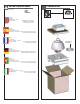
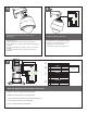
! Electrical Specifications Power 24VAC Class 2 Only 24 VAC 3.2 Amps Total Power: 75 Watts Tools Required: English Contents of Box EXPF7 EXSS7 EXSP7 EXRHW(P)7 .100” Flat Head Screwdriver Phillips Head Screwdriver 7/16” Wrench or Socket 24 VAC 3.2 amperios Energía Total: 75 vatios Las Herramientas Requirieron: Destornillador Principal Plano Del 100" Destornillador Principal Phillips Español 24 VCA 3.
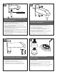
1 2 1 ➟ 1” Straight Conduit Wall mount bracket is designed for straight conduit. If this fitting is desired, install it first. Otherwise, use the thru mount wiring provision. • Soporte de pared está diseñado para conducción recta. Si se desea este ajuste, se debe instalar primero. De lo contrario, utilice el suministro de cableado de montaje a través. • Support mural est conçu pour les conduit tout droit. Si cette mise en place est souhaitée, d'abord l'installer.
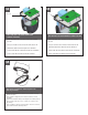
5 6 Secure lanyard from dome housing to clip on wall mount. Complete all wiring connections. • Acollador seguro de la bóveda que contiene al clip en el montaje de la pared. • Termine todas las conexiones del cableado. • Lanière bloquée du dôme logeant à l'agrafe sur le bâti de mur. • Schließen Sie alle Verdrahtungsanschlüsse ab. • Sichere Abzuglinie von der Haube, die zum Klipp auf Wandeinfassung unterbringt. • Termine todas as conexões da fiação. • Accomplissez tous les raccordements de câblage.
9 X3 PLACES Engage the thread and rotate housing assembly clockwise into wall mount fitting until tight. Fasten trim ring assembly to main housing with a phillips screwdriver. • Enganche el hilo y gire conjunto de la caja hacia la derecha en el accesorio de montaje en pared hasta que quede apretado. • Sujete el montaje del anillo del ajuste a la cubierta principal con un destornillador Phillips. • Engager le fil et tourner ensemble boîtier dans le sens horaire dans le raccord mural en serrant bien.
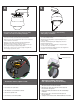
12 SD Card Slot SD card slot is located at the base of Pan / Tilt unit. 13 SD Card SD card slot is located at the base of Pan / Tilt unit. • Ranura para tarjetas SD se encuentra en la base? De la unidad Pan / Tilt. • Ranura para tarjetas SD se encuentra en la base? De la unidad Pan / Tilt. • Fente pour carte SD se trouve à la base? De l'unité de Pan / Tilt. • Fente pour carte SD se trouve à la base? De l'unité de Pan / Tilt. • SD-Kartensteckplatz an der Basis liegt der Pan / Tilt-Einheit.
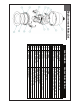
Replacement Parts List 1 2 3 4A 4B 5 6 7 8 9 10 11 12 13 14 N/S RPVL4025 RP76VL2024 RPVL3414 RP762030 RP76ENE100 RPFD072 RPFD080 RPVL4106 RP762021 RPEX4281 RPVL4028 RP96RSRG16 RP96RS0RG23 PART NUMBER HOUSING SURGE/CONNECTION PCB HGS BKT PCB NETWORK DAUGHTER PCB PCB-NETWORK CARD PCB HEATER 24VAC BLOWER EXO BASE BKT TILT PCB LINER ASSEMBLY 2 PARTS CLAMPING RING(S) INNER O-RING 8" OUTER O-RING 9" CLEAR NYLON DOME STAINLESS LOWER TRIM RING SUNSHIELD PRODUCT DISCRIPTION RPVL4024 RPVL4029
SOFTWARE SETUP 1.0.0 Moog Discovery Tool By factory default, the Moog EXO Camera is configured in DHCP. If you are not using a DHCP server it will automatically allocate itself an APIPA (Automatic Private IP Addressing) address in the range 169.254.0.1 to 169.254.255.254 with subnet mask 255.255.0.0. Initial device network configuration is done via the Moog Discovery Tool (MDT), a tool provided by Moog that can be found on the company’s web site and on the flash drive supplied with each camera system.
To configure the Unicast Discovery, add one or more IP address ranges. The Unicast Discovery tries to reach a device at a specific IP address in the configured ranges. The discovery can be a long process if the range of IP addresses is large and the device is at the end of the range. To accelerate the discovery, add several small ranges of IP addresses. The ping timeout option can be increased for a high latency network.
To assign IP Address, update firmware, or configure Moog web interface, right click on highlighted serial number / Mac Address. Assign IP Address(es) Once the IP information is set, the Silverlight web application served by the EXO Camera can be launched from the MDT or directly in your web browser by typing the device’s IP address in the address bar.
2.0.0 Using the Moog EXO Web Application Application When entering the Web Application, the following window will be displayed. You will be asked a username and password. The default User name and Password is ‘admin’.
2.1.0 System Status Status Window 1. System Status - 2.1.0 2. Configuration - 2.2.0 3. Maintenance - 3.0.0 4. Live Viewer - 4.0.0 5. Recording - 5.0.0 Main Menu Tabs Upon successfully logging into the web interface, a welcome screen will be displayed. The welcome screen shows general devices health status as well as firmware version and system uptime.
2.2.0 System Configuration Configuration / System Under the Configuration section, select the System tab to perform the following operations: • View product model information, current firmware version and serial number. • Specify a custom name; this name can be used by third-party software to display a selected name for the device. - Enable edge recording by checking the box “Use Recorder Module” checkbox. Disabling edge recording will accelerate the device’s boot time.
2.2.1 Configuration / Date Time Under the Configuration section, select the Date Time tab to perform the following operations: • Set the time zone in which the device is operating. • Manually set the current date and time for the device’s internal clock. • Note: For an accurate time stamp, you must sync UTC Time. 2.2.
2.2.3 Configuration / Network / DHCP Under the Configuration section, select the Network tab to perform the following operations: • Set the encoder’s IP parameters; DHCP or static IP information. • Configure an NTP server to allow the device to automatically update its internal clock using an NTP server. 2.2.4 Configuration / Network / Host Name Configuration-NPT NPT Server- use when desiring to have local network time as default, to do so you must……. 2.2.
2.2.6 Configuration / Network / API- Boujour NOTE: • To control the EXO Camera system with a VMS software system, you must enable the required Network APIs. Enable PSIA or GENETEC API depending on which VMS platform you intend to use with the device. Disabling any unrequired APIs will accelerate boot time. Milestone VMS will link through the PSIA API. • Note: ONVIF is standard built in and does not require activation. If using ONVIF you do not need to select an API.
2.3.0 Configuration / Video In 2.3.1 Configuration / Video In / Video Input Under the Configuration section, select the Video In tab to perform the following operations: Digital format – choices are, 720 30fps, 720 60fps, 1080 30fps, 1080 25fps. Note max camera output with WDR Active is 15fps (1080p). 2.3.2 Configuration / Video In / Sensor Configure camera bloc / sensor parameters.
(Note: Activating WDR at 1080P will reduce maximum frame rate to 15fps.) Configure video compression parameters for any of the three available codec instances (Primary H.264, Secondary H.264 and MJPEG). Most VMS software solutions will interact with these parameters and thus it is suggested to leave these at default values in the web interface. VBR aggressiveness however is unique to Moog EXO Cameras and proposes various levels (disabled to aggressive) of motion triggered rate control.
2.3.4 Configuration / Video In / Point to Point • Configure point to point video connections (up to three) for creating persistent video streams from the encoder to a network endpoint. 2.3.5 Configuration / Video In / Text Overlay Text Box To insert a text overlay: • There are (2) available strings (Text blocks). Select string. • Select string Size. • For string position click mouse inside string position box. o Text bar will appear on video image.
2.3.6 Configuration / Video In / Motion Detection Select from 1 of 4 available regions: • With mouse click on region position box. • Bring mouse pointer to view window and drag box around area for motion detection. • Select desired Frame Count, Sensitivity and Thresholds. • Press “Save” button to store information. • You can select up to (4) separate “Motion” windows.
2.3.7 Configuration / Video In / Privacy Zones Privacy Zones are used to block out video in areas view is not permitted or desired. To add a Privacy Zone: • Select the Zone to be identified with privacy area. There are up to 16 zones available. • With the mouse, click on Privacy Zone Position Box. • Move mouse pointer over the Image Window, click and draw a box on the area you wish to see video. • Press the “Save” button to store.
2.3.8 Configuration / Audio In Under the Configuration section, select the Audio In tab to perform the following operations: • Configure audio input compression parameters. • Configure point to point audio connections (up to three) for creating persistent audio streams from the encoder to a network endpoint.
2.3.9 Configuration / Audio Out Under the Configuration section, select the Audio Out tab to perform the following operations: • Configure audio output parameters. • Configure a point to point audio connection for receiving a persistent audio stream from a network endpoint.
2.4.0 Configuration / Recording Note: Recording Menu will NOT be visible unless activated; see 2.20 System configuration. • Grooming mode; Select method to remove files from full SD card chronological will remove old files first.
2.4.1 Configuration / User Accounts Under the Configuration section, select the User Accounts tab to perform the following operations: • Select the web interface’s authentication method. A dual passphrase is made available for additional security. • Manage user accounts which have access to the device.
3.0.0 Maintenance This section describes how to update your Moog EXO Cameras to newer firmware versions from the web application. 1. To find the latest file go to www.videolarm.com/technical-support/. 2. Click on “EXO PTZ Camera Firmware” - click, save file. 3. Navigate to your device’s web application using your favorite web browser. 4. Click on the Maintenance tab. 5. Click on the Update button, locate downloaded firmware. You will be asked for the firmware update file; please select the .
4.0.0 Live Viewer Use Live View for: • Live Camera View • Start and Stop Recording • Pan / Tilt and Camera Control • Setting Presets • Adjust View Scale To enable live you must activate by pressing the “Play” button. Play Button To adjust viewing scale for 1024 x 768 monitor, press scale view.
4.1.0 Live Viewer Pan / Tilt and Presets Pan/Tilt Controls Lens Control Preset Controls • Pan Tilt Control; To operate Press Arrow in desired direction of movement. • Use Pan / Tilt speed slinder controls to vary Pan / Tilt speed control, to increase speed, slide control knob to (?) • Lens Funtion use +/- buttons to update Iris, Zoom and Focus. • Preset Functions. • o First Select Preset No. o Then position Camera and lens to desired position o Press “Set” to save Preset.
5.0.0 Recording To activate recording mode you must go to Configuration / System / Use Recorder Mode. Click “Use Recorder Mode” checkbox. This will activate addional Recording controls in the recording window. You must “Save” and then “Reboot” after making this change > Select Video Input > Select Date of the Recording Then select the filed clip you wish to view Note: You must have either VLC Player or Windows Media Player installed.
6.0.0 Performing Batch Firmware Update This section describes how to perform a batch update of multiple Moog EXO Camera devices to newer firmware versions from the MDT. The batch firmware update works by starting a firmware update session. Only one session at time is allowed and only 20 devices can be selected by session. From the MDT, select one or more devices of the same type. By using the right mouse button on the selected devices, choose the “Firmware Update” menu option.
To start a firmware update session, choose the “.iof” file corresponding to the new firmware by clicking to the “Select File …” button. Once selected, click to the “Start” button. Once started, the “Firmware Update Session” window shows the progress of the firmware update. This window can be closed at any moment without losing the current session.
If closed, the progress of the current session can be followed by reopening the “Firmware Update Session” window by clicking the from the “Tools” toolbar. button Once done, clear the current session from the “Firmware Update Session” window and restart a new session if needed. 7.0.0 Point to Point Connections Point-to-point connections between an Moog EXO Camera and an Decoder can be configured using the device’s web application.