
User`s manual


APPENDIX C – RESTART INTERLOCK CIRCUITS C-8
CDS7324 (FORMERLY LSF-0819)
Rev. A INSTALLATION & USER’S MANUAL
C.5.1 Wiring practice
The external cable to RESTART INTERLOCK connector must be protected against mechanical damages
according to the safety requirements of EN ISO 13849-2:2003, tab. D.4 (prEN 954-2) in order to prevent short
circuits.
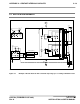
The Restart Interlock relay of Channel 1 is controlled using the external +24Vdc (pin2 positive terminal, pin1 0V
terminal).
When the RL1 relay is de-energized, pins 5-6 are closed and the Restart Interlock Channel 1 is activated.
If “Channel 2” is used, the Restart Interlock relay of Channel 2 is controlled using the external +24Vdc (pin4
positive terminal, pin3 0V terminal).When the RL2 relay is de-energized, pins 7-8 are closed and the Restart
Interlock Channel 2 is activated.
If “Channel 2” is not used, the relays (RL2) of “Channel 2” must be always powered using the external +24Vdc
(pin4 positive terminal, pin3 0V terminal).
WARNING - The auxiliary functions circuit (NO contacts) must be externally protected using either
a delayed fuse rated 2 A or a fast fuse rated 3 A
WARNING - Pins 1 and 3 must be connected to the protective bonding circuit to prevent
malfunctions in case of earth faults.