
User`s manual


APPENDIX B – GUI B-35
CDS7324 (FORMERLY LSF-0819)
Rev. A INSTALLATION & USER’S MANUAL
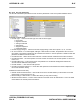
B.2.16.34 Encoder Parameters
The Encoder Parameters panel allows the user to set the parameters of this motor position feedback sensor.
ENCODER PARAMETERS :
• Encoder Type → Select the encoder type from a list of various types:
9 No Encoder
9 Digital Incremental
9 Analog Incremental
9 SSI Interface
9 Stegmann Hiperface
9 Heidenhain EnDat
• Encoder Supply Voltage → Choose the encoder supply voltage. There are 3 options: +5, +8, +12 Volts.
• No. of Increments → For normal digital, analogue or SSI interface encoders, the parameter has to be set to
the number of increments (optical lines) per mechanical revolution. In case of Hiperface or Endat encoder this
parameter is obtained from the encoder.
• Encoder Direction → Select the encoder’s direction of rotation between Clockwise and Counter-clockwise.
• Encoder Resolution → Fix the bit position of the full encoder increments in the encoder position. It can be set
from 2 to 31.
• Encoder Offset (incs.) → This can be used to compensate for a mechanical misalignment between the
encoder and the desired encoder position.
• Encoder Position → The 32-bit encoder position.
• Encoder Commutation Position → A 16-bit value that represents a full mechanical revolution independent of
the encoder resolution setting.
Parameters for SSI Encoder Only
• Number Of Bits For SSI Interface → The number of bits in the raw data stream (not the number of encoder
position bits). It can be set from 2 to 32.
• Data Encoding For SSI Interface → Select either binary or Gray code encoding.
• Bit Mask For SSI Interface → Used to mask off all the unused bits in the raw data stream. A one in the mask
means that the bit contains position information`