
User`s manual


CHAPTER 5.0 Functional Overview 5-47
CDS7324 (FORMERLY LSF-0819)
Rev. A INSTALLATION & USER’S MANUAL
5.11.4 Control Loop Configuration
The control loops are configured by setting/unsetting bits in an internal mode request to switch in/out the various
control loop elements. The mode request can be configured for each of the modes of operation: position, velocity
and torque, by setting the appropriate mode preset parameter.
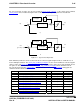
The table below describes the bits that can be set in the mode request to configure the control loops:
NOTE: Any bit defined as a value (1 or 0) must be always set to that value.
BIT Definition
31 (MSB) 0
30 0
29 0
28 0
27 0
26 0
25 0
24 0
23 0
22 0
21 0
20 0
19 0
18 0
17 0
16 0
15 1
14 0
13 0
12 0
11 0
10 acceleration limiting enable
9 command micro-interpolation
8 gain calibration
7 time-optimal position loop enable (otherwise PI loop)
6 position mode
5 field weakening enable
4 observer enable
3 generic filter enable
2 0
1 velocity mode
0 (LSB) torque mode
Table 5.33 mode request bit definitions
5.11.4.1 Torque Mode Preset
The parameter control_loop_torque_mode_preset
(1334) sets the mode request when a torque control mode is
requested. The default value for this parameter is 33041 (8111 hex) indicating that bits 0, 4, 8 and 15 are set.
Note that the bit 0 must always be set in this parameter, bits 1 and 6 must never be set and bits 3, 7 and 10 have
no meaning in torque mode.