
User`s manual


CHAPTER 5.0 Functional Overview 5-40
CDS7324 (FORMERLY LSF-0819)
Rev. A INSTALLATION & USER’S MANUAL
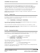
Velocity Limit
torque
100%
actual velocity
1.05 * Velocity Limit
5 %
Automatic or Manual
Mode Limit
Figure 5.9 : Velocity limiting when in Torque Mode
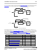
5.11.2.4 Velocity Loop Filter
The generic filter has 9 programmable parameters. Therefore, it may be configured as hi-pass, low-pass, band-
pass or band-stop, to allow for maximum flexibility. The output of the velocity compensator becomes the input to
the generic filter, denoted by current_demand_velocity_comp_output (1120). The output of the generic filter is
current_demand_generic_filter_output (1122). These two parameters may be monitored on the GUI scope to
view the filter activity in real time. The filter may be included/excluded by setting/clearing the appropriate bit in the
control loop configuration (see section 5.11.4)
NOTE
: The default filter operating period is velocity_loop_rate_divider / switching_frequency = 4/9920 = (approx
400 μs).
The Generic filter that is implemented is listed below, where
)(kyf is the filter output, and )(ky is the filter input
at a particular sample instant k.
()
()
)4()3()2()1()(
)4()3()2()1()(
43210
4321
−×+−×+−×+−×+×
+
−
×
+
−
×
+
−
×+−×−=
kybkybkybkybkyb
kyfakyfakyfakyfakyf
The filter has the following set of parameters: -
Field
Number
Name Type
1351 velocity_loop_filter_coefficient_a1 F32
1352 velocity_loop_filter_coefficient_a2 F32
1353 velocity_loop_filter_coefficient_a3 F32
1354 velocity_loop_filter_coefficient_a4 F32
1355 velocity_loop_filter_coefficient_b0 F32
1356 velocity_loop_filter_coefficient_b1 F32
1357 velocity_loop_filter_coefficient_b2 F32
1358 velocity_loop_filter_coefficient_b3 F32
1359 velocity_loop_filter_coefficient_b4 F32
1360 velocity_loop_mode F32
Table 5.30 List of Filter Parameters