
User`s manual


SECTION 1: DS2100 OVERVIEW
DS2100 User's Manual
C27750-001 PAGE 1-5
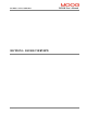
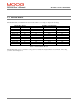
G361 X X X XX X - XX - XXX
Model Series Designator
Current Model Design Status
Fieldbus / command reference
Status
-
Available
-
-
Power Rating Section
No.
Arms / Apk
03 3/11
06 6/22
08 8/22
14 14/42
20 20/45
25 25/70
30 30/90
50 50/140
60 60/180
10 100/300
10
4
100/300
11
5
100/300
11
4, 5
100/300
Current Hardware Version
Software Version
P/N
C27735-001
Reserved
C27745-100
C27745-100
C25699-011 C27741-001 C27745-100
Reserved
Description
C25699-006
Control Stage
C25699-025
C25699-030
C25699-020
C25699-003
C25699-110 C27741-001
See form 757 for valid configurations (Default 000)
C27741-001
C27741-001
C27741-001
C27741-001
C27741-001
C27741-001
CA18517-508-000R
C25699-050
C25699-060
0
C27741-001
C27740-001
C27740-001
4
3 Reserved
CA18516-503-000R
Power Stage
Safety Interlock
XXX
Number
Letter
A
Version
Letter
Reserved
2
CAN
Reserved
E (E model)
- (dash)
1
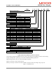
Option DescriptionNo.
Packing Kit
C27745-003
C27745-003
C27745-014
C27745-008
C27745-100
C27745-050
C27745-020
C27745-020
C27745-020
C27745-050
No.
0
Option
No Safety Interlock
1 Safety Interlock installed.
03 Standard CAN Software
C25699-010 C27741-001
Description
C25699-111 C27741-001
Valid Controller Model Numbers: Reference Form 757
1)Users must be experienced/qualified in the use of this product range before building products from this drawing.
2)3Amp and 6Amp drive options are provided with a 120Ohm Internal Regen Resistor
3)External regen resistors are to be ordered and supplied separately.
4)These power stages contain a safety interlock.
5)These power stages contain an AC mains/ 24V PSU to directly feed fans, when high-voltage is present.
Figure 1.1 DS2100 Box Car