
User`s manual


DS2100 User's Manual
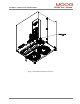
SECTION 3: WIRING AND INSTALLATION
PAGE 3-2 C27750-001
TABLE OF CONTENTS
SECTION 3:
WIRING AND INSTALLATION ................................................................................................. 3-1
3.1
System Components .................................................................................................................................. 3-4
3.1.1
A.C. Mains Power Interface............................................................................................................... 3-4
3.1.2
A.C. Input Line Protection................................................................................................................. 3-5
3.1.3
Line Filter Requirements ................................................................................................................... 3-5
3.1.4
Serial Set-up Terminal (User-Supplied) ............................................................................................ 3-7
3.1.5
Control-Backup Power Input (User Supplied)................................................................................... 3-7
3.1.6
Brushless Servo motors ..................................................................................................................... 3-7
3.1.7
Heatsinks and Climatic Control ......................................................................................................... 3-8
3.2
Equipment Mounting ................................................................................................................................. 3-9
3.2.1
CE Items for Mechanical Installation .............................................................................................. 3-17
3.3
Power Dissipation.................................................................................................................................... 3-18
3.4
DS2100 Connector Terminals ................................................................................................................. 3-19
3.5
General System Wiring Guidelines ......................................................................................................... 3-23
3.5.1
Drive Contactor (User Supplied) ..................................................................................................... 3-24
3.5.2
Wiring notes for J6, J7, J9 connectors (Size C) ............................................................................... 3-25
3.6
Sequence of Component Wiring Recommendations ............................................................................... 3-26
3.7
Three-Phase A.C. Mains Power Source Configuration ........................................................................... 3-27
3.7.1
AC Mains Power Source Connection .............................................................................................. 3-29
3.7.2
Softstart & Power Cycling Frequency Limits.................................................................................. 3-33
3.8
24V Backup Connection.......................................................................................................................... 3-34
3.8.1
Size µA 24V Input Connection........................................................................................................ 3-34
3.8.2
Size A,B,C, D & E 24V Input Connection ...................................................................................... 3-35
3.8.3
Auxiliary 24V Fan connection (Size E)........................................................................................... 3-36
3.9
Paralleling DS2100 Units through the D.C. Bus ..................................................................................... 3-37
3.9.1
µA Size DC Bus Inter-connection ................................................................................................... 3-37
3.9.2
A & B Size DC Bus Inter-connection.............................................................................................. 3-38
3.9.3
C Size DC Bus Inter-connection...................................................................................................... 3-39
3.9.4
D Size DC Bus Inter-connection...................................................................................................... 3-40
3.9.5
E Size DC Bus Inter-connection ...................................................................................................... 3-41
3.10
Internal/External Regeneration (Regen) Resistors – Configurations ....................................................... 3-42
3.10.1
µA Size Regeneration Resistor Connection..................................................................................... 3-43
3.10.2
A, B Size Regeneration Resistor connection ................................................................................... 3-43
3.10.3
C Size Regeneration Resistor connection ........................................................................................ 3-44
3.10.4
D Size Regeneration Resistor connection ........................................................................................ 3-45
3.10.5
E Size Regeneration Resistor connection ........................................................................................ 3-46
3.11
Motors - Installation ................................................................................................................................ 3-47
3.11.1
Assembling Motor Resolver and Power Cables............................................................................... 3-47
3.11.2
Motor Power Cable.......................................................................................................................... 3-48
3.11.3
Motor Brake Connection ................................................................................................................. 3-54
3.11.4
Motor Resolver Connection............................................................................................................. 3-57
3.11.5
Motor Encoder Connection.............................................................................................................. 3-60
3.11.6
Motor Rotation Direction................................................................................................................. 3-62
3.12
DS2100 Control Input and Outputs ......................................................................................................... 3-63
3.12.1
General Purpose Description of the Digital Inputs .......................................................................... 3-64
3.12.2
General Purpose Description of the Digital Outputs........................................................................ 3-66
3.12.3
Power Sequencing on Startup .......................................................................................................... 3-68
3.13
Communications Interface Wiring and Configuration............................................................................. 3-69
3.13.1
RS232 Serial Communications Interface......................................................................................... 3-69
3.13.2
CAN Cable Wiring .......................................................................................................................... 3-70
3.14
Wiring Summary ..................................................................................................................................... 3-73
3.14.1
µA Size Power Stage ....................................................................................................................... 3-73
3.14.2
A & B Size Power Stage.................................................................................................................. 3-74
3.14.3
C Size Power Stage.......................................................................................................................... 3-75
3.14.4
D Size Power Stage.......................................................................................................................... 3-76