
User`s manual


APPENDIX B: GUI DS2100 User's Manual
C27750-001 PAGE 53
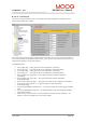
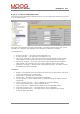
B.3.16.38 Position TO Loop Compensators
The Position TO Loop Compensators panel allows the user to set the configuration of the TO loop gains
and to see the feedback values.
The time-optimal compensator is a non linear compensator that uses a square root function of the position
error, to give optimal deceleration performance.
CONFIGURATION
• Ka-gain (rad/s^2) → The a-gain of the TO compensator (rad/s^2).
• Kp-gain (Ki) → The p-gain of the TO compensator (1/s).
• K i-gain (Kp) → The i-gain of the TO compensator (1/s^2).
• Vel. Pi comp. p-gain (Kp) → The p-gain of the velocity loop PI compensator used in position
mode (Nm/rad/s). This is separate to the velocity loop compensator used in velocity mode.
• Vel. Pi comp. i-gain (Ki) → The i-gain of the velocity loop PI compensator used in position
mode (Nm/rad). This is separate to the velocity loop compensator used in velocity mode.
• position loop rate divider → The rate divider of the position loop mode – the number of current
loop samples per position loop sample.
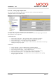
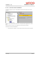
FEEDBACK
• demand → The requested value of the position.
• position (rad) → The actual value of the position
• time opt. comp. error → The difference between position and demand.
• velocity command → velocity command prior to acceleration limiting (the output from the PI
compensator)
• velocity command (previous) → velocity command after acceleration limiting
• actual velocity (filtered) (rad/s) → low pass filtered velocity
• extd vel. comp. error → difference between actual velocity and demanded velocity
• torque cmd (vel comp o/p) (A) → the output from the velocity compensator
• torque cmd (gen filter o/p) (A) → the output from the velocity compensator after passing
through the generic filter block