
User`s manual


DS2100 User's Manual APPENDIX B: GUI
PAGE 34
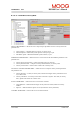
B.3.16.23 DS402 Interpolated Position Mode
This mode is used to control multiple coordinated axles or a single axle with the need for time-
interpolation of set-point data. The IP Mode uses the sync object as a synchronization mechanism for
coordination of the related drive units. For each interpolation cycle, the drive will calculate a position
demand value by interpolating positions over a period.
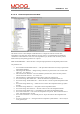
IMPUT PARAMETERS → Allows the user to setup the input parameters of interpolated position mode.
The parameters are:
• Inter. Data Record Size/Position/Time → The input data words that are necessary to perform the
interpolation algorithm.
• SW. Range Limit Min/Max → Range limiting on demand, in position units. The extreme fixed
values are –2^31 and 2^31 –1.
• SW. Position Limit Min/Max→ Limit on demand in position units, relative to home position.
The extreme fixed values are –2^31 and 2^31-1.
• Max Load Speed → Maximum speed of the system, used in the velocity loop.
• Inter. Data Config. Max. Buffer Size → Shows the maximum interpolation buffer size
• Inter. Data Config. Actual Buffer Size → Allows the user to set the required interpolation buffer
size.
• Inter. Data Config. Buffer Org. → Allows the user to select the interpolation buffer type (FIFO
or Ring).
• Inter. Data Config. Buffer Pos. → The position in the interpolation buffer.
• Inter. Data Config. Size of Record → The size of each record in the interpolation buffer.
• Inter. Data Config. Buffer Clear → Clear/disable or else enable the interpolation buffer.
• Inter. Time Period Units → The size of the interpolation time period. This is defined in units of
‘Inter. Time Period Index’ seconds.
• Inter. Time Period Index → The seconds power of 10 per unit used for the interpolation time
period.
• Inter. Sync Defn Sync on → The signal used for interpolation synchronisation – this can only be
set to ‘general sync’