
User`s manual


APPENDIX B: GUI DS2100 User's Manual
C27750-001 PAGE B-31
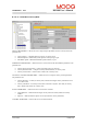
B.3.16.21 DS402 Direct Position Mode
In this mode, a target position is set and limited to create a position demand. No profile generator is used.
INPUT PARAMETERS → Allows the user to setup the input parameters of direct position mode. The
parameters are:
• Target Position → Input Position for absolute move, in position units.
• SW. Range Limit Min/Max → Range limiting on demand, in position units. The extreme fixed
values are –2^31 and 2^31 –1.
• SW. Position Limit Min/Max→ Limit on demand in position units, relative to home position.
The extreme fixed values are –2^31 and 2^31-1.
• Max Load Speed → Maximum speed of the system, used in the velocity loop.
• Home Offset → Delta between the zero position and the home position (found during homing),
in position units.
• Position Window → Delta between target and actual position, if less than or equal to this
window, (in position units) it will set the target reached bit in the status word.
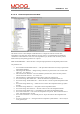
FEEDBACK PARAMETERS → Allows the user to see the value of the four feedback parameters. The
parameters are:
• Position Demand Value → Output from Demand Block in position units.
• Position Demand Value* → Output from Demand Block in units of increments.
• Position Actual Value → Actual value from the position measurement device, in position units.
• Position Actual Value* → Actual value from the position measurement device, in incs.
STATUS WORD BITS → Allows the user to see the status word bits.
• Target Reached → Indicates that the target velocity has been reached, within the velocity
window.
• Set Point Acknowledge → Indicates if the Drive has assumed the positioning values or not.
CONTROL WORD BITS → Allows the user to set the control word bits.
• New Set – Point → Set the next target position.
• Change Set Immediately → Interrupt the actual positioning and then start the next positioning.