
User`s manual


DS2100 User's Manual APPENDIX B: GUI
PAGE B-16 C27750-001
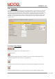
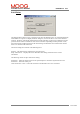
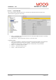
B.3.16.6 Control with Step Function Generator
The Control of Drive with Step Function Generator panel allows the user to control the drive directly
from the GUI and use the internal step function generator to set the command into the loop.
• Drive Mode Status → This displays the current mode of the drive. This may be blank if the drive
is not being controlled using this panel. On start-up the drive defaults to standby mode (1306).
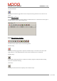
• Mode Control → These buttons allow the user to set the drive mode.
• Function Generator Setup → This allows the user to set the function generator Amplitude,
Offset, Period and Duty Cycle commands. The units of amplitude and offset are changed
according to the controller mode (position – rad, velocity – rad/s, torque – Nm).
• Maximum current → This parameter allows the user to see the maximum current capability of
the drive/motor system to assist with using the function generator with the drive in torque mode.
• Maximum velocity → This parameter allows the user to see the maximum velocity capability of
the drive/motor system to assist with using the function generator with the drive in velocity
mode.