
User`s manual


APPENDIX A: DATA LOGGER
DS2100 User's Manual
C27750-001 PAGE A-5
A.1.3.3 Trigger input
The trigger input is selected by setting the trigger channel parameter trigger_field_number to the field number of the
parameter that is used for triggering the sampling process. The coupling is selected by setting the trigger_coupling
(index 0x2f04, subindex 3) parameter:
0x00 - ac coupled trigger input
0x01 - dc coupled trigger input
0x02 - bitmask trigger
The trigger level can be set with the trigger_level_xxxxx parameters. The data type has to match the data type of the
parameter sampled. For example, if a 16-bit integer value is used for triggering, then trigger_level_16-bit has to be set.
The trigger levels also hold the bit mask for the bit mask trigger mode. Only bits that are 1 in the mask are used for
triggering. More than one bit can be set to one.
The trigger slope parameter trigger_slope (index 0x2f04, subindex 4) selects if triggering is done on the rising or falling
edge of the trigger input. If bit mask trigger is used a 0-1 transition is taken as a rising and a 1-0 transition is taken as a
falling input signal.
0x01 - trigger on rising edge
0x02 - trigger on falling edge
0x03 - trigger on both edges
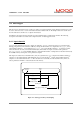
Normally the sampling would start at the trigger event. If the sampling has to be delayed, or if the samples shall be taken
before the trigger event, the position of the trigger event within the samples can be selected using the trigger delay
parameter trigger_delay (index 0x2f04, subindex 11). It holds the number of the samples before the trigger event.
A.1.4 Data Access
A.1.4.1 Scaled data access
To improve performance and to make the interface easier there are parameters available that allow the reading of scaled
data for each channel with only one byte per channel and sample transmitted.
The offset data_logger_scaling_offset (index 0x2f06, subindex 1 - 4) is added to the value and the result is then
multiplied with the scaling factor data_logger_scaling_factor (index 0x2f05, subindex 1 - 4). The result is then rounded
to the nearest signed 8-bit value and can be accessed by reading the parameter data_logger_channel_x. The number of
bytes transmitted is always DLGDIS (500). The transmitted data can be selected from the sampled data by writing to the
parameter data_logger_sample_number (index 0x2f07, subindex 1) before reading the data which represents the number
of the first data sample to be transmitted relative to the trigger position.