
User`s manual


DS2100 User's Manual
APPENDIX A: DATA LOGGER
PAGE A-4 C27750-001
A.1.2 Time base
The data logger normally runs at the main interrupt frequency of the controller (PWM frequency) or a fraction of this.
The main interrupt frequency can be read with the parameter data_logger_sample_frequency (index 0x2f00, subindex
2). The divider ratio can be set with the parameter data_logger_divider_factor (index 0x2f00, subindex 1). The resulting
sample frequency is then data_logger_sample_frequency / data_logger_divider_factor.
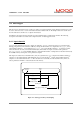
A.1.3 Trigger
The trigger controls the sampling of the data syncronized to a trigger input which can be any of the 8-, 16-, 24- or 32-bit
integer or 32-bit or 64-bit floating point parameters. It is possible to have a delayed trigger or pre-trigger. The possible
trigger coupling can be dc, ac or bitmap masking, the slope can be rising, falling or both.
A.1.3.1 Trigger modes
The parameter trigger mode trigger_mode (index 0x2f04, subindex 1) controls the trigger and the sampling. There are
four different trigger modes available:
0x00 - free running trigger: always sampling
0x01 - normal trigger: waiting for trigger event and start sampling, retriggerable
after sampling has finished
0x02 - single shot trigger: after trigger event only one set of samples taken
0x03 - stopped: no samples taken
A.1.3.2 Trigger status
The actual trigger status can be read back reading parameter trigger_status (index 0x2f04, subindex 13). It has one of
the four possible values:
0x00 - system is beeing initialised; data logging not possible
0x01 - waiting for trigger event
0x02 - sampling
0x03 - ready, sampled data can be accessed
The samples can be only read from the data logger memory when the trigger status is ready. In single shot triggering the
data logger will go automatically into the ready state. In free running mode or normal trigger mode the data trigger mode
has to be set to stopped. After finishing the sampling, the data logger will then automatically go into the ready state.