
User`s manual


APPENDIX A: DATA LOGGER
DS2100 User's Manual
C27750-001 PAGE A-3
A.1 Data Logger
The data logger is an internal storage oscilloscope with up to four input channels, trigger function and time base. It can
be used to store fast events or to store information that caused fault conditions. The sampled data can be downloaded
from the embedded controller onto a computer and analysed.
Normally the data logger functions should be used from within the Moog graphical user interface. The following
description is intended for users that want to implement their own data logger front-end.
A.1.1 Input channels
Up to four input channels can be used to sample any internal 8-, 16-, 24- or 32-bit wide integer or 32-bit and 64-bit
floating point parameter. The channel is enabled by writing the field number to be sampled into data_logger_channel
(index 0x2f02, subindex 1 - 4) and setting the data_logger_enable (index 0x2f01, subindex 1 - 4) parameter to 0x01,
where the index into the array is the channel number (0-3). The number of samples to be taken is the parameter
data_logger_memory_size (index 0x2f00, subindex 3). The maximum number of samples that can be taken is limited by
the available memory and depends on the parameters sampled.
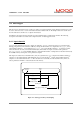
The samples are written into an internal memory array in sequential order, e.g. 1
st
sample of first enabled channel, 1
st
sample of second enabled channel, until all channels are processed and then 2
nd
sample of first enabled channel 2
nd
sample of second enabled channel and so on. The data cannot be read directly from the internal memory. There are
various parameters available to extract the data from the memory.
internal data logger memory
samples taken
continously
trigger
event
data_logger_memory_size
data_logger_data
DLGDIS (500)
data_logger
sample_number
Figure A.1: data logger memory and sampling