
User`s manual


SECTION 7: CANOPEN DRIVE PROFILE : DS402 DS2100 User’s Manual
C27750-001 PAGE 7-61
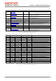
6. The default operation of the limit switches is to be active low. This can be inverted by inverting the
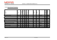
associated digital input. In addition a parameter called home logical switch status word (0x2858/0)
contains the logical status of these digital inputs, and be can used to see which inputs are set, regardless of
the digital input mapping.
Figure 7.31 Home logical switch status parameter
7. A non-DS402 parameter called home position can be read to display the home position. This value is in
increments, and is the value of “position actual” sampled when the homing cycle is complete.
8. The Position Polarity is not used during homing mode. This is not explicitly stated in the DS402 standard,
but similar modes are available for left and right moves (e.g. method 1, and 2.)
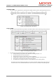
9. The user can set a home offset that defines the position of the “zero position” relative to this home position.
Profile and Interpolated Position moves are relative to this zero position. Position Limits are however
relative to the home position. Parameters such as Position Actual Value (0x6064), Position Demand
(0x6062) etc, are also relative to the zero position.
Figure 7.32 Homing position co-ordinates
10. The DS402 standard indicates that as well as setting the error bit in the status word, that an error code could
be written. This is not done; instead the home error state can be used.
11. The home position is NOT saved to non-volatile memory, since it is assumed that a homing cycle is done
initially on power-up.
12. The home offset is saved to non-volatile memory. This means that following power-up, if this value is non-
zero, a move with a target position of zero, would still result in the movement of the axis, by the home
offset amount.
13. In case where large velocities are used during homing. There may be a noticeable reversal of direction
when switch or zero position is hit, due to the requirement to return to the registered position when the
switch or zero was hit.
14. If the homing cycle is interrupted e.g. by causing a shutdown, instead of clearing the “start operation bit”,
no error is indicated, since mode specific bits are only examined when in enabled state.
3 2 1 0
Home Switch
N
egative Limit Switch
Positive Limit Switch
-2147483648 2147483647 0
Internal Co-Ordinates (Incs)
User Co-Ordinates (incs, pos units.)
Hompos (incs)
Home Offset (pos units)
Zero Position
Soft Position Limits (pos units)
Moves are relative to the
Zero Position