
User`s manual


DS2100 User’s Manual SECTION 7: CANOPEN DRIVE PROFILE: DS402
PAGE 7-60 C27750-001
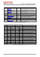
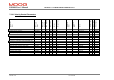
Val. State Description
2 Check neg. limit switch Error since neg. limit switch set, before move
3 Check pos. limit switch Error since pos. limit switch set, before move
5 Set up neg. limit switch Error since no digital input set up for neg. limit switch
6 Set up pos. limit switch Error since no digital input set up for pos. limit switch
7 Set up index pulse Error since pos. feedback != encoder, or Enc. Inc. = 16384.
8 Set up home switch Error since no digital input set up for home switch
18,23,24 Check zero registration Error since zero pos. is with error window revs. of switch pos.
- - If set halt bit in control word.
- - If Homing start bit in control word, 1->0, during homing.
- - Homing attempts to execute NULL function.
Table 7.22 Table of homing error state values
GENERAL ISSUES
1. If the drive is disabled via the serial text interface the profile generator can still generate the profile, which
can result in high speeds, when the drive is enabled, due to large position errors.
2. An internal limit in the drive may limit the acceleration further. This drive acceleration limit parameter (in
rads/sec) has a default value of 1000000rads/sec. This limit is also used for quick-stopping the drive.
3. In the case of 1, 2, 17 and 18, if the limit switch is active at the start, no movement occurs and the error bit
is indicated in the status word.
4. Changing homing method during a homing move is not recommended, it may only lead to confusion. The
method is sampled at the start of the homing move.
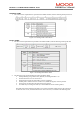
5. The user must configure the digital inputs so that the correct digital input handler function is associated
with the required digital input. This is achieved by writing the number of the digital input handler function
to the relevant correct element in the “diginpcfg” entry. The array is zero indexed, with entry 0 always
configured for the enable input. The DS402 Digital inputs parameter (0x60FD) has not been implemented
since the digital inputs are user configurable. The following are the function numbers
Digital Input Handler Example
Positive Limit Switch 6 Diginpcfg[1] 6 (i.e. 0x2C2E/3 ) sets input 1 to positive limit switch
Negative Limit Switch 7 Diginpcfg[2] 7 (i.e. 0x2C2E/5 ) sets input 2 to negative limit switch
Homing Switch 8 Diginpcfg[3] 8 (i.e. 0x2C2E/7 ) sets input 3 to homing switch
Table 7.23 Table of digital input configuration values