
User`s manual


DS2100 User’s Manual SECTION 7: CANOPEN DRIVE PROFILE: DS402
PAGE 7-54 C27750-001
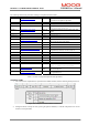
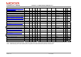
SAMPLE SETUP
The following section gives an example of a typical setup for an interpolated position move. It fills the buffer with 5
set-point position of 0,20,40,60, and 80 degrees, and in a ring buffer, cycles through these set-points :-
Index/Sub Index Name Value Comment
0x6040 ds402 control word 0x06 Shutdown command
0x6060 ds402 mode of operation 7 Set Interpolated Position Mode
0x60C2/1 interpolation time period units 250 interpolation period = 250mS
0x60C2/2 interpolation time period index -3
0x60C4/5 interpolation data configuration record size 1
0x60C4/2 interpolation data configuration actual buffer size 5 Only 5 entries in the buffer
0x60C4/3 interpolation data configuration buffer organisation 1 Set-up for Ring Buffer
0x60C4/6 interpolation data configuration buffer clear 0 Clear out the buffer
0x60C4/6 interpolation data configuration buffer clear 1 Enable access to input buffer
0x60C4/4 interpolation data configuration buffer position 0 Set buffer position
0x60C1/1 interpolation data record set point 0 Write set-point
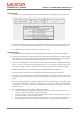
0x60C4/4 interpolation data configuration buffer position 1 Move buffer position
0x60C1/1 interpolation data record set point 20 Write Position = 20
0
0x60C4/4 interpolation data configuration buffer position 2 Move buffer position
0x60C1/1 interpolation data record set point 40 Write Position=40
0
0x60C4/4 interpolation data configuration buffer position 3 Move buffer position
0x60C1/1 interpolation data record set point 60 Write Position=60
0
0x60C4/4 interpolation data configuration buffer position 4 Move buffer position
0x60C1/1 interpolation data record set point 80 Write Position=80
0
0x6040 ds402 control word 0x1F Enable the drive and the mode.
Table 7.19 Sample set-up for interpolated position mode