
User`s manual


SECTION 7: CANOPEN DRIVE PROFILE : DS402 DS2100 User’s Manual
C27750-001 PAGE 7-51
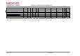
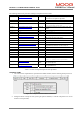
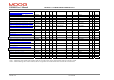
The following table lists the parameters relating to Interpolated Position Mode.
Index Name Type Comment
0x60C1 interpolation data record. Array The input data words that are necessary to
perform the interpolation algorithm
0x60C1/0 number of entries S32 1 or 2, depending on record size (0x60C4/5)
0x60C1/1 set point S32 Target position for the velocity loop.
0x60C1/2 period. S32 Interpolation period if record size=2. In units of
time period index (0x60C2/2).
0x60C2 interpolation time period Record Interpolation period in terms of time units, and
index.
0x60C2/0 number of entries U08 Fixed Value = 2
0x60C2/1 units U08 Default value = 1
0x60C2/2 index S08 Default value = -3
0x60C3 interpolation sync definition Array Configure synchronization of drives, on every
nth occurrence of a Sync Object.
0x60C3/0 number of entries U08 Fixed Value = 2
0x60C3/1 synchronize on U08 Default value = 0, (i.e. General Sync is used)
0x60C3/2 sync every U08 Default value = 1, used in FIFO mode.
0x60C4 interpolation data configuration Record Configures Max./Actual Buffer Size,
Organisation, Position, size of record, etc.
0x60C4/0 number of entries U08 Fixed Value = 6
0x60C4/1 max buffer size U32 Default value = 256
0x60C4/2 actual buffer size U32 Default value = 256 (DS402 indicates 0)
0x60C4/3 buffer organisation U08 Default value = 0 (0=FIFO, 1=Ring)
0x60C4/4 buffer position U16 Default value = 0
0x60C4/5 size of data record U08 Default value = 1
0x60C4/6 buffer clear U08 Default value = 0. (0=clear buffer, disable
access, 1= enable access to input buffer)
0x2855 interpolation buffer Array of
S32
Internal array, which holds the data records that
are written by user.
0x2856/2 interpolation sync count U32 Counter of Syncs received, since buffer cleared
or organisation set.
Table 7.18 Table of interpolated position mode parameters
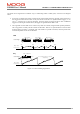
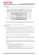
CONTROL WORD
1. The control word is implemented as specified in the DS402 standard, with the following mode specific bits
Figure 7.26 Interpolated Position Mode Control Word.
2. Setting the halt bit will stop the axle, by fixing the position demand (i.e. hold the read pointer at its current
location in the input buffer).