
User`s manual


SECTION 7: CANOPEN DRIVE PROFILE : DS402 DS2100 User’s Manual
C27750-001 PAGE 7-49
7.17 Interpolated Position Mode
The Interpolated Position Mode is used to control multiple coordinated axles or a single axle with the need for time-
interpolation of set-point data. The Interpolated Position Mode uses the sync object as a synchronization mechanism
for coordination of the related drive units. For each interpolation cycle, the drive will calculate a position demand
value by interpolating positions over a period of time.
Due to real-time requirements, the scaling and limiting of the interpolation data record is done when placing the data
in the input buffer. This differs from the diagram in the DS402 standard that suggests that the scaling and limiting is
done in real-time. The mode is implemented using linear interpolation only, and does not include the optional limit
functions for speed, acceleration and deceleration. Instead the buffer can be seen as a set of position set points for
the position loop.
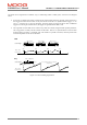
Figure 7.24 Interpolated Position Mode implementation.
The mode is implemented by writing data records into a buffer. The user writes into the data records, which in turn
are written into the buffer. The data records can either have 1 or 2 entries. Single entries contain the position set
points. Records with 2 entries contain set point, and a time period. In the case of single entry records, the
interpolation period is defined in the interpolation period parameter. In the case of records with 2 entries, the
interpolation unit is defined in the data record, but the interpolation index (e.g. 10
-3
, or 10
-2
, is still read from the
interpolation period parameter.)
Homing
Function
Position
Control Loop
Multiplier
Limiter
Interpolation Data Configuration
Pos. Factor + Polarity
Software Position Limits,
Position Range Limits,
Home Offse
t
Interpolation Data Record
Input
Buffer
Real-Time
Interpolation
Interpolation Time Period
Interpolation Sync Definition
Position
Feedback