
User`s manual


SECTION 7: CANOPEN DRIVE PROFILE : DS402 DS2100 User’s Manual
C27750-001 PAGE 7-13
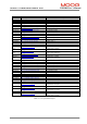
Bits 0…3, and Bit 7 in the control word control the transitions between the drive states. The table below lists the
commands that are issued by setting the appropriate control word bits.
Bit of the control word
Command
Brake
control
Fault
Reset
Enable
operation
Quick stop
Enable
voltage
Switch on
Transitions
Shutdown X 0 X 1 1 0 2,6,8
Switch on X 0 0 1 1 1 3*
Switch on X 0 1 1 1 1 3**
Disable voltage X 0 X X 0 1 7,9,110,12
Quick stop X 0 X 0 1 X 7,10,11
Disable
operation
X 0 0 1 1 1 5
Enable
operation
X 0 1 1 1 1 4,16
Fault reset X
↑
X X X X 15
Apply Brake
↑
X X X X X In any
state***
Release Brake
↓
X X X X X In any
state***
Figure 7.5 Control Word Commands/Transitions
Bits marked X are irrelevant except that a transition on ‘brake control’ will always cause the indicated action
* … In the state SWITCHED ON the drive executes the functionality of this state
** … No functionality in the state SWITCHED ON
*** .. The brake control will cause the indicated action except in the START or NOT READY TO SWITCH ON
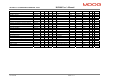
The status word describes the state of the drive. The tables below lists the meaning of each bit, with later sections
outlining the operation mode specific bits, and the state of the drive, indicated by the settings of these bits.
Bit Description
0 Ready to switch on
1 Switched on
2 Operation enabled
3 Fault
4 Voltage enabled
5 Quick stop
6 Switch on disabled
7 Warning
8 Not used
9 Remote
10 Target reached
11 Internal limit active
12 – 13 Operation mode specific
14 Not used
15 Brake applied