
User`s manual


SECTION 6:CANOPEN INTERFACE DS2100 User's Manual
C27750-001 PAGE 6-17
6.9 Synchronisation
The synchronisation method in CANopen is implemented through synchronisation messages that are sent by a sync
producer (normally a PLC controller) and that are received by the drive(s).
Time
CAN Bus
Activity
Receive
PDOs
Sync
message
Transmit
PDOs
Receive
PDOs
Sync
message
Transmit
PDOs
PLC
Activity
Drive
Activity
Time
Time
receive
actual
values
calculate
new
demand
values
transmit
new
demand
values
transmit
new
demand
values
receive
actual
values
receive
new
demand
values
Drive
transmit
PLC
transmit
transmit
actual
values
receive
new
demand
values
transmit
actual
values
Conmmunication
cycle period
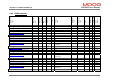
Figure 6.5 Typical CAN system
The picture shows a typical CAN system in Operational state with the PDOs and synchronisation messages sent in a
cyclic manner. In every cycle the PLC controller receives the actual values, calculates the new demand values and
transmits the new demand values to the drive(s). Then the synchronisation message enables the new demand values
in the drive(s) and the new actual values are sampled and transmitted via the bus.
The communication identifier (cob-id) of the synchronisation messages can be changed with the parameter
sync_message_cob-id (index 0x1005, subindex 0). The time in between sync messages is called communication
cycle period. It can be changed by writing to the parameter sync_communication_cycle_period
(index 0x1006,
subindex 0). It contains the synchronisation time in microseconds. The maximum allowed timeout between
synchronisation messages is sync_communication_cycle_period
multiplied by 1.5. If a different timeout value is
desired, the parameter sync_maximum_number_missing
(index 0x2005, subindex 0) can be used. If it is set to a
non-zero value, the synchronisation timeout is sync_communication_cycle_period
multiplied by
sync_maximum_number_missing
. If sync_maximum_number_missing is set to zero, the timeout is
sync_communication_cycle_period
multiplied by 1.5