
User`s manual


DS2100 User's Manual SECTION 5: DS2100 FUNCTIONAL OVERVIEW
PAGE 5-64
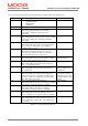
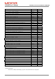
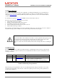
A list of warnings and faults that should be indicated are detailed in Table 5.38 and Table 5.39.
Display Warning Description Drive Reaction
.
Current limiting Active : due to
Thermal Foldback
Manual Mode
I
2
t limiting
Current limited
U1 High Power Not Ready – softstart mode Drive will not enable
U2 Motor Thermal Warning :
This warning indicates that the motor winding
temperature is within 10% of the motor max
temperature.
Current limited
U3 Power Amplifier Thermal Warning:
This warning indicates that the power transistor heatsink
temperature is within 10% of the bridge maximum
temperature.
Current limited
U4 Regeneration Power Warning :
This warning indicates that the power dissipated in the
regen resistor(s) is within 10% of the continuous
capability of the resistor(s).
None
U5 Position Tracking Warning :
This warning indicates that the position error has
exceeded a pre-set threshold. This error will only be
present when the drive is in position mode.
None
U6 Limit Switch Warning :
This warning indicates that either clockwise or counter
clockwise limit switch has become active.
Cannot move in
particular direction.
U7 24V Backup Supply Warning :
This warning indicates that Logic supply is below 18
Volts, or greater than 32 Volts.
None
U8 Manual Mode:
This warning indicates that user has switch the drive
into manual mode.
Current and velocity
limited to limman % of
normal limits.
U9 Enable Attempted Warning:
This warning indicates that the user has attempted to
enable the drive from a no fault state, but with at least
one of the conditions for enable false (e.g. H/w enable
false, Bus voltage not present)
Drive will not enable.
Note that this warning
will remain present once
set until the drive is truly
enabled
U10 Power Amplifier Thermal Limit Warning:
This warning indicates that the power transistor heatsink
temperature is causing the current to be limited
Current limited
U11 Motor Thermal Limit Warning:
This warning indicates that the motor winding
temperature is causing the current to be limited
Current limited
U12 Ambient Thermal Limit Warning:
This warning indicates that the ambient (control card
sensor) temperature is causing the current to be limited
Current limited
U13 Ambient Thermal Warning :
This warning indicates that the ambient (control card
sensor) temperature is within 10% of the ambient max
temperature.
Current limited
Table 5.38 7-Segment Warning Idication