
User`s manual


DS2100 User's Manual SECTION 5: DS2100 FUNCTIONAL OVERVIEW
PAGE 5-62
5.12 Drive Monitoring & Fault Detection
5.12.1 Drive Monitoring
The DS2100 monitors a range on internal and external drive voltages, temperatures, times and powers to ensure that
the drive is operating correctly. Depending on the state of these feedback signals, the drive will react appropriately
to ensure safe and reliable operation of the drive. The parameters monitored are listed below.
Temperatures
Parameter Name Index / Subindex Description
bridge_temperature 0x2802 / 5 Power Amplifier Bridge Temperature
motor_temperature 0x2802 / 10 Motor Winding Temperature
ambient_temperature 0x2802 / 15 Control Electronics Ambient Temperature
Table 5.33 Monitored Temperatures
Voltages
Parameter Name Index / Subindex Description
supply_+24V 0x2810 / 25 Internal 24V Logic Supply
supply_+3V3 0x2810 / 5 3.3V Logic Supply
supply_-15V 0x2810 / 10 -15V Logic Supply
supply_+15V 0x2810 / 15 +15V Logic Supply
supply_+2V_ref. 0x2810 / 20 2V Reference Level
encoder_ supply 0x2810 / 30 Encoder Supply
bus_voltage_actual 0x60F7 / 18 DC Bus Voltage
Table 5.34 Monitored Voltages
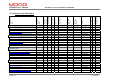
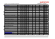
Times (Elapsed time Indicator)
Parameter Name Index / Subindex Description
ETI_total_power_on_time 0x2A03 / 1 Total powered up time
ETI_power_on_time_since_power_on 0x2A03 / 2 Power up time since power up
ETI_number_of_power_downs 0x2A03 / 3 Number of power downs
ETI_enabled_time 0x2A03 / 4 Total enable time
ETI_enabled_time_since_power_on 0x2A03 / 5 Enabled time since power up
ETI_enabled_time_since_enable 0x2A03 / 6 Current enabled time
Table 5.35 Monitored Times
Power
Parameter Name Index / Subindex Description
regen_power_filtered 0x24A4 / 5 Average Regeneration Power (Measured)